Modularized planar antenna structure

a planar antenna and module technology, applied in the field of antennas, can solve the problems of high manufacturing cost, time-consuming assembly of the first electronic device, and achieve the effect of reducing cost and assembling effor

Active Publication Date: 2008-09-25
CIROCOMM TECH CORP
View PDF4 Cites 12 Cited by
  • Summary
  • Abstract
  • Description
  • Claims
  • Application Information

AI Technical Summary

Benefits of technology

[0005]It is an object of the present invention to provide a modularized planar antenna structure, wherein the antenna structure can be directly surface soldered to a main circuit board of an electronic device while the planar antenna structure still keeps directivity toward zenith. The modular design can reduce cost and assembling effort.

Problems solved by technology

However, the electronic devices s integrated with GPS unit shown in FIG. 1 has time consuming assemble and high manufacture cost.

Method used


Image

  • Modularized planar antenna structure
  • Modularized planar antenna structure
  • Modularized planar antenna structure

Examples


Embodiment Construction

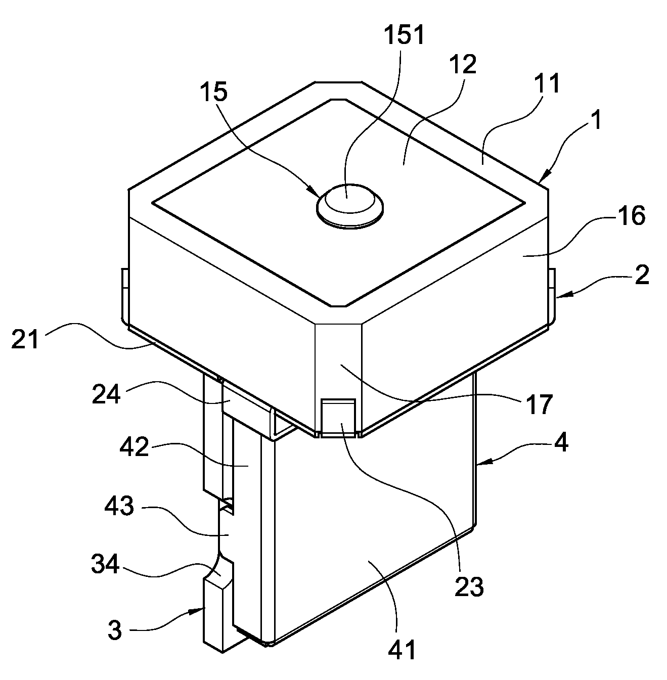
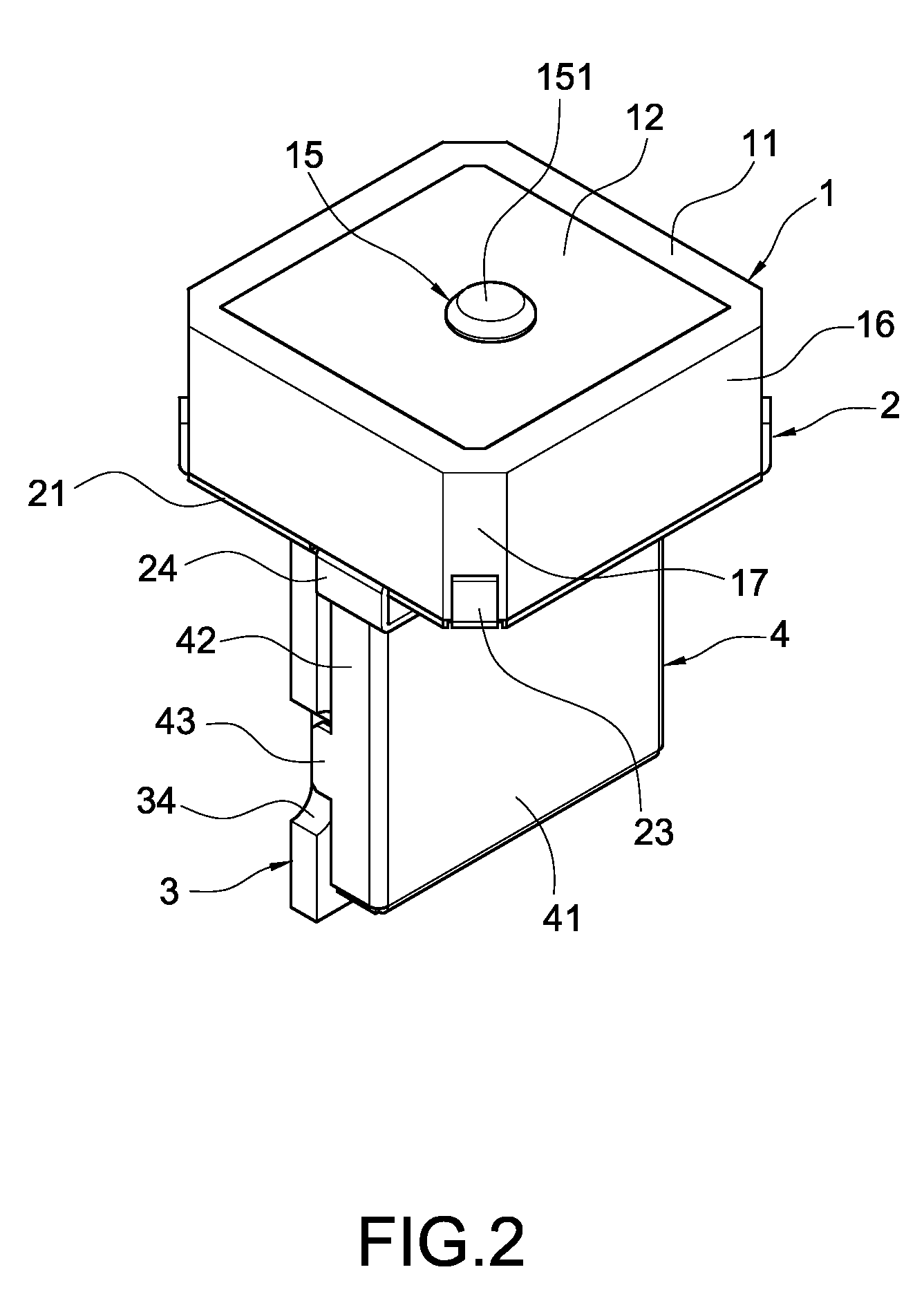
[0021]With reference to FIGS. 2 and 3, the modularized planar antenna of the present invention comprises an antenna unit 1, a connection unit 2, a circuit board 3 and a cover 4. The connection unit 2 connects the antenna unit 1 and the circuit board 3 such that the antenna unit 1 is vertical to the circuit board 3.

[0022]The antenna unit 1 is a square planar antenna and comprises a ceramic base 11 with a radiation metal plate 12 on top surface thereof and a ground metal plate 13 on bottom thereof. A through hole 14 is defined on the ceramic base 11, the radiation metal plate 12 and the ground metal plate 13, and a T-shaped signal feeder 15 passes through the through hole 14. The T-shaped signal feeder 15 comprises a hemisphere first end 151 for electrically connecting to the radiation metal plate 12. A second end 152 of the T-shaped signal feeder 15 passes the ground metal plate 13. The second end 152 of the T-shaped signal feeder 15 is not electrically connected to the ground metal ...


PUM


Abstract

A modularized planar antenna structure includes an antenna unit, a connection unit, a circuit board and a cover. The modularized planar antenna structure connects the antenna unit and circuit board. The antenna unit includes a signal feeder electrically connected the circuit board at end thereof such that the antenna unit is vertical to the circuit board. The cover is assembled to the circuit to protect the circuit board from electromagnetic interference or strike of external article. When the antenna structure is assembled to a main circuit board of an electronic device, the circuit board can be directly assembled to the main circuit board of an electronic device and the circular-polarized antenna unit points toward zenith direction to receive satellite signal.

Description

FIELD OF THE INVENTION[0001]The present invention relates to an antenna, especially to an antenna for receiving satellite signal.DESCRIPTION OF PRIOR ART[0002]GPS is the acronym of “Global Position System”, which uses trigonometry positioning principle and measures distance by transmission time of wireless signal. At least three satellites are used to calculate the distances between them and target and positioning of target can be obtained by built-in map in the GPS receiver.[0003]The current vehicle navigation system is developed to incorporate with vehicle video system and can be implemented in the form of PDA, Notebook computer and mobile phone. Among them, the most attractive is the portable Global Position System (portable GPS). The portable GPS can be easily installed in car without equipping with GPS system and can be used in another car or off the car.[0004]When the GPS unit is integrated with electronic devices such as PDA, Notebook computer and mobile phone, the electronic...

Claims


Application Information

Patent Timeline
Patent Type & Authority Applications(United States)
IPC IPC(8): H01Q1/24
CPCH01Q1/12H01Q9/0428H01Q1/243
Inventor YANG, TSAI-YICHU, TE-YI
Owner CIROCOMM TECH CORP
Why Eureka
Try Eureka