Aerodynamic error reduction for liquid drop emitters

a drop emitter and liquid drop technology, applied in the direction of printing, inking apparatus, etc., can solve the problems of not being completely predictable, affecting the volume of drops intended for printing or patterning, and a large number of jets, and achieve the effect of reducing errors and high speed

Active Publication Date: 2008-09-25
EASTMAN KODAK CO
View PDF19 Cites 32 Cited by
  • Summary
  • Abstract
  • Description
  • Claims
  • Application Information

AI Technical Summary

Benefits of technology

[0025]It is therefore an object of the present invention to provide methods of depositing high qua...

Problems solved by technology

Such satellites may not be totally predictable or may not always merge with another drop in a predictable fashion, thereby slightly altering the volume of drops intended for printing or patterning.
The several CIJ stimulation approaches disclosed by Sweet '275 may all be practical in the context of a single jet system However, the selection of a practical stimulation mechanism for a CIJ system having many jets is far more complex.
Unfortunately, all of the stimulation methods employing a vibration of some component of the printhead structure or a modulation of the common supply pressure result in some amount of non-uniformity of the magnitude of the perturbation applied to each individual jet of a multi-jet CIJ array.
Non-uniform stimulation leads to a variability in the break-off length and timing among the jets of the array.
This variability in break-off characteristics, in turn, leads to an inability to posit...

Method used


Image

  • Aerodynamic error reduction for liquid drop emitters
  • Aerodynamic error reduction for liquid drop emitters
  • Aerodynamic error reduction for liquid drop emitters

Examples


Embodiment Construction

[0063]The present description is directed in particular to elements forming part of, or cooperating more directly with, apparatus in accordance with the invention. Functional elements and features have been given the same numerical labels in the figures if they are the same element or perform the same function for purposes of understanding the present invention. It is to be understood that elements not specifically shown or described may take various forms well known to those skilled in the art.

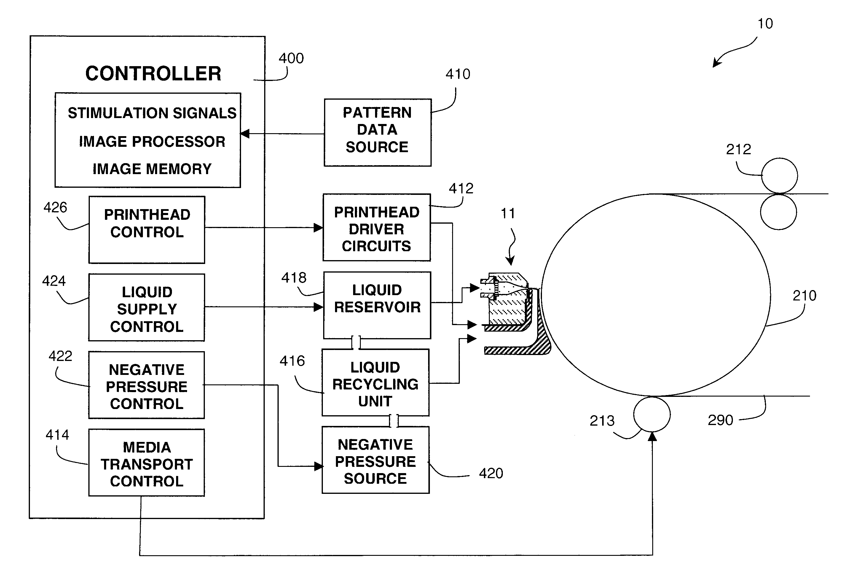
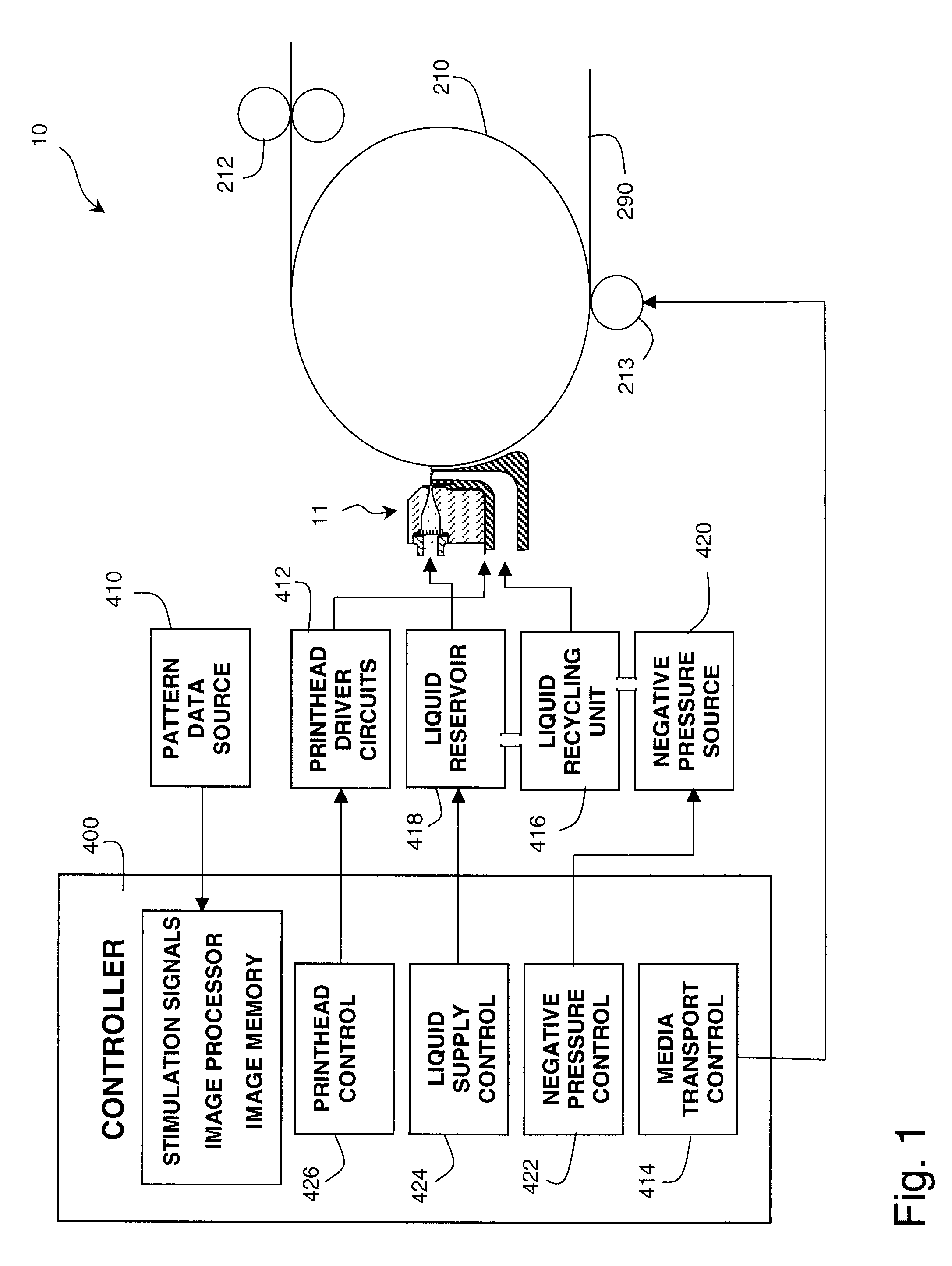
[0064]Referring to FIGS. 1 and 2, a continuous drop deposition apparatus 10 for depositing a liquid pattern is illustrated. Typically such systems are ink jet printers and the liquid pattern is an image printed on a receiver sheet or web. However, other liquid patterns may be deposited by the system illustrated including, for example, masking and chemical initiator layers for manufacturing processes. For the purposes of understanding the present invention the terms “liquid” and “ink” will be ...


PUM


Abstract

A method is disclosed for forming a liquid pattern of print drops impinging a receiving medium according to liquid pattern data using a liquid drop emitter that emits a plurality of continuous streams of liquid at a stream velocity, vd, from a plurality of nozzles having effective diameters, Dn, arrayed at a nozzle spacing, Sn, along a nozzle array direction that are broken into a plurality of streams of print and non-print drops by a corresponding plurality of drop forming transducers to which a corresponding plurality of drop forming energy pulse sequences are applied. The method is comprised of forming non-print drops by applying non-print drop forming energy pulses during a unit time period, τ0, and forming print drops by applying print drop forming energy pulses during a large drop time period, τm, wherein the large drop time period is a multiple, m, of the unit time period, τm=mτ0, and m≧2; and a corresponding plurality of drop forming energy pulses sequences are formed so as to form non-print drops and print drops according to the liquid pattern data. The corresponding drop forming energy pulse sequences applied to adjacent drop forming transducers are substantially shifted in time so that the print drops formed in adjacent streams of drops are not aligned along the nozzle array direction. Also disclosed is a drop deposition apparatus for laying down a patterned liquid layer on a receiver, according to the disclosed methods, wherein the plurality of nozzles are grouped and shifted to partially or fully compensate for the shift in print position caused by the time shift of energy pulse sequences.

Description

FIELD OF THE INVENTION[0001]This invention generally relates to digitally controlled printing devices and more particularly relates to a continuous ink jet printhead that integrates multiple nozzles on a single substrate and in which the breakup of a liquid ink stream into printing drops is caused by an imposed disturbance of the liquid ink stream.BACKGROUND OF THE INVENTION[0002]Ink jet printing has become recognized as a prominent contender in the digitally controlled, electronic printing arena because of its non-impact, low-noise characteristics, its use of plain paper and its avoidance of toner transfer and fixing. Ink jet printing mechanisms can be categorized by technology as either drop-on-demand ink jet or continuous ink jet.[0003]The first technology, “drop-on-demand” ink jet printing, provides ink droplets that impact upon a recording surface by using a pressurization actuator (thermal, piezoelectric, etc.). Many commonly practiced drop-on-demand technologies use thermal a...

Claims


Application Information

Patent Timeline
IPC IPC(8): B41J2/02
CPCB41J2/03B41J2002/022B41J2202/16B41J2002/033B41J2002/14403B41J2002/031
Inventor BROST, RANDOLPH C.
Owner EASTMAN KODAK CO
Why Eureka
Try Eureka