Imager and method for consistent repeatable alignment in a solid imaging apparatus

a solid imaging apparatus and imager technology, applied in the field of solid imaging apparatus and methods, can solve the problems of excessive moving parts, unresolved numbers, and requiring a large amount of effort, and achieve the effect of less post-build cleaning and curing

Active Publication Date: 2008-09-25
3D SYST INC
View PDF56 Cites 58 Cited by
  • Summary
  • Abstract
  • Description
  • Claims
  • Application Information

AI Technical Summary

Benefits of technology

[0015] Thus, the invention provides, among other things, a desk top modeler for flexible transport solid imaging providing removable and replaceable consumable components of build material and transport film in a single container. The invention provides a desk top modeler that can make builds that require less post-build cleaning and curing and can produce a fully reacted, tack-free build. The invention also provides several subassemblies that can be adapted individually for use in connection with other solid imaging apparatus and methods.

Problems solved by technology

Despite the variety of devices and methods developed for solid imaging, a number of drawbacks have yet to be resolved.
The apparatus and methods for practicing solid imaging tend to be somewhat characterized by excessive moving parts and complex systems that can require a good deal of effort to service, maintain, and operate.
Laser imaging and UV imaging systems tend to be costly and to place these systems out of reach for many applications.
Complex, tedious alignment steps for aligning the radiation source and the image plane reduce efficiency and increase cost.
The large vats of liquid resin used in stereolithography are expensive and can become contaminated with pieces of cured resin.
Solid imaging devices typically produce “green” three-dimensional products, in which uncured build material wets the surface and causes the product to be tacky and to require cleaning prior to fully curing the product throughout the build.

Method used


Image

  • Imager and method for consistent repeatable alignment in a solid imaging apparatus
  • Imager and method for consistent repeatable alignment in a solid imaging apparatus
  • Imager and method for consistent repeatable alignment in a solid imaging apparatus

Examples


Embodiment Construction

[0094] This invention can best be understood with reference to specific embodiments that are illustrated in the drawings and the variations described herein below. While the invention will be so described, it should be recognized that the invention is not intended to be limited to the embodiments illustrated in the drawings. On the contrary, the invention includes all alternatives, modifications, and equivalents that may be included within the scope and spirit of the invention as defined by the appended claims.

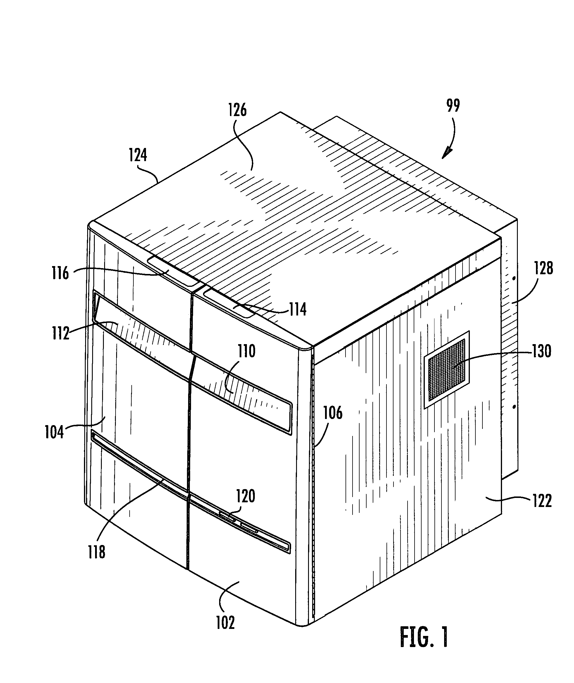
[0095]FIG. 1 illustrates in a perspective view generally at 99 one embodiment of a housing for a desk top modeler of the invention. Housing 99 includes right and left hand hinged doors 102, 104. The hinge for door 102 can be viewed at 106. Door 102 is provided with handles 110, 114 and door 104 is provided with handles 112, 116 on the door face and top, respectively. It should be recognized that a wide variety of such arrangements profitably can be used, a primary requirement...


PUM

PropertyMeasurementUnit
thickaaaaaaaaaa
thickaaaaaaaaaa
thicknessaaaaaaaaaa

Abstract

A solid imaging apparatus is provided that includes a replaceable cartridge containing a source of build material and an extendable and retractable flexible transport film for transporting the build material layer-by-layer from the cartridge to the surface of a build in an image plane. An operator using the device needs merely to remove a spent cartridge and replace it with a fresh cartridge to continue solid imaging virtually uninterrupted. The apparatus also includes the capability of withdrawing and inserting an imager without the operator having to perform a separate alignment step. A brush attached to the transport film and forming part of the cartridge provides for intra-layer removal of excess uncured build material. If desired, the apparatus can produce a fully reacted build. A high intensity UV source cures the build between layers. An injection molded build pad is designed to hold a build in an inverted position for improving the build. The invention also provides for tilting the build elevator to reduce air entrainment and for releasing the build from the image plane.

Description

CROSS-REFERENCE TO RELATED APPLICATIONS [0001] This application claims priority from Provisional Application Ser. No. 60 / 885,257 filed Jan. 17, 2007 for “Solid Imaging Apparatus and Method Including: Cartridge for Solid Imaging Apparatus; Method for Conveying Build Material Layer-By-Layer; Elevator for Tilting Solid Image Build Platform for Reducing Air Entrainment and for Consistent Repeatable Alignment in a Solid Imaging Apparatus;” Provisional Application Ser. No. 60 / 949,614 filed Jul. 13, 2007 for “Solid Imaging Apparatus and Method Including: Cartridge for Solid Imaging Apparatus; Method for Conveying Build Material Layer-by-Layer; Elevator for Tilting Solid Image Build Platform for Reducing Air Entrainment and for Build Release; Build Platform, Solid Image, and Method for Solid Imaging; Imager and Method for Consistent Repeatable Alignment in a Solid Imaging Apparatus; Eccentric Reciprocating Brush and Method for Reducing Overbuild; and Provisional Application Ser. No. 60 / 956,...

Claims


Application Information

Patent Timeline
Patent Type & Authority Applications(United States)
IPC IPC(8): H04N5/217
CPCB29C67/0062B29C67/0055B29C71/04B33Y10/00B33Y30/00B29C64/106B29C64/124B33Y50/02
Inventor HULL, CHARLES W.PARTANEN, JOUNISPERRY, CHARLES R.SCOTT, SUZANNE M.MCNAMARA, DENNIS F. JR.
Owner 3D SYST INC
Why Eureka
Try Eureka