
Treatment method of lithium ion battery material powder sample section

A lithium-ion battery and processing method technology, which is applied in the field of processing the cross-section of lithium-ion battery material powder samples, can solve the problems of low utilization efficiency of G1 glue, uneven dispersion of powder particles, and changes in sample morphology, etc., to achieve economical sample preparation The effect of time, high sample utilization rate, and complete cross-sectional shape information

Active Publication Date: 2020-10-16
HEFEI GUOXUAN HIGH TECH POWER ENERGY
View PDF7 Cites 4 Cited by
  • Summary
  • Abstract
  • Description
  • Claims
  • Application Information

AI Technical Summary

Problems solved by technology

This method has certain limitations, and the disadvantages are as follows: 1. The powder sample is embedded in G1 glue, the powder is too dispersed, the sample utilization efficiency is low, and there are few sample particles that can be observed in the microscopic field of view
2. G1 glue is non-conductive, and the main component of the sample after curing is non-conductive G1 glue, which will cause a charging effect when observed under a scanning electron microscope, and the test effect is not good; sometimes it is necessary to spray a conductive layer, and the commonly used methods such as spraying gold will change the shape of the sample to a certain extent
3. The price of G1 glue is very expensive. After embedding the sample, in order to meet the size requirements of ion beam cutting, it still needs to be polished after rough grinding, which increases the workload and causes low utilization efficiency of G1 glue.
4. During the embedding process, during the heating and curing process, the powder particles will sink to the bottom of the resin, which will cause uneven dispersion of the powder particles, resulting in only a few particles in the upper resin, which is not conducive to microscopic observation

Method used


Image

  • Treatment method of lithium ion battery material powder sample section
  • Treatment method of lithium ion battery material powder sample section
  • Treatment method of lithium ion battery material powder sample section

Examples


Embodiment 1

[0030] Argon Ion Beam Section Cutting of Ternary Precursor Materials

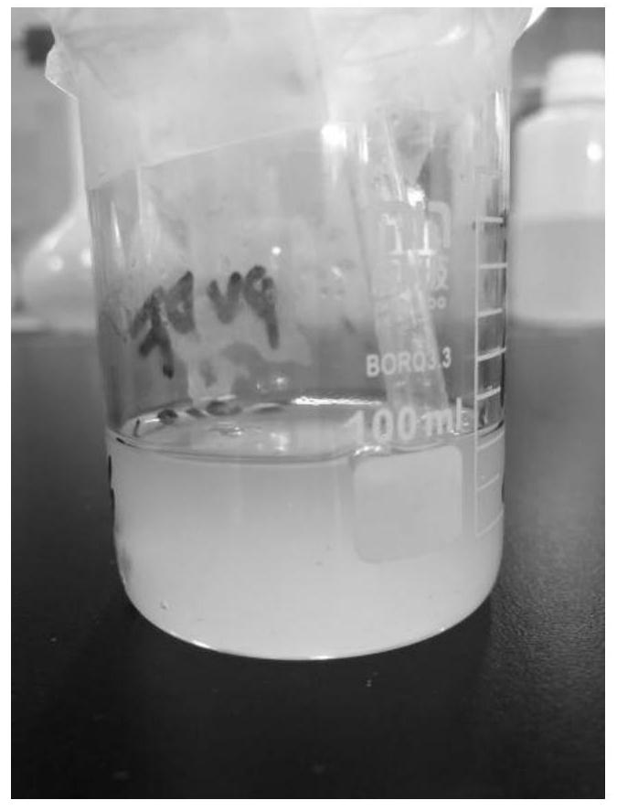
[0031] S1. Weigh 2.0g of PVDF powder into a clean beaker, add 38.0g of NMP solvent, and stir for 4 hours until translucent viscous glue is obtained, such as figure 1 shown;

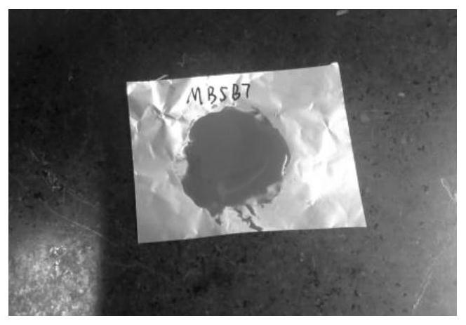
[0032] S2. Cut off an appropriate amount of copper foil, use a dropper to draw about 0.5mL of glue solution and place it on the surface of the copper foil, add 1.75g ​​of the precursor powder sample to be tested, mix the powder evenly in the PVDF glue with a toothpick, and use a spatula to evenly mix the glue Coated on the surface of copper foil, the coating thickness is 50μm, such as figure 2 shown;

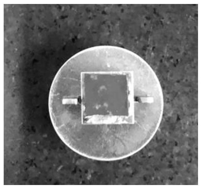
[0033] S3. Put the coated copper foil in an oven at 90°C. After 30 minutes, after the adhesive layer is volatilized and dry, cut a 0.5×0.5cm copper foil with a uniform mixture, and solidify the powder sample from the copper foil. Remove it from the foil, and fix it on the baffle used for argon ion beam cutting through the sample load...

Embodiment 2

[0035] Argon Ion Beam Section Cutting of Ternary Precursor Materials

[0036] S1. Weigh 2.0g of PVDF powder into a clean beaker, add 32.0g of NMP solvent, and stir for 6 hours until translucent viscous glue is obtained;

[0037] S2. Cut off an appropriate amount of copper foil, use a dropper to absorb about 0.5mL of glue and place it on the surface of the copper foil, add 2.25g of the precursor powder sample to be tested, mix the powder evenly in the PVDF glue with a toothpick, and use a spatula to evenly mix the glue Coated on the surface of copper foil, the coating thickness is 10μm;

[0038] S3. Put the coated copper foil in an oven at 85°C. After 30 minutes, after the adhesive layer has evaporated and dried, cut a 0.5×0.5cm copper foil with a uniform mixture, and remove the solidified block of the powder sample from the copper foil. Remove it from the foil, and fix it on the baffle used for argon ion beam cutting through the sample loader; put the prepared sample into the...

Embodiment 3

[0040] Argon Ion Beam Section Cutting of Ternary Precursor Materials

[0041] S1. Weigh 2.0g of PVDF powder into a clean beaker, add 38.0g of NMP solvent, and stir for 4 hours until translucent viscous glue is obtained;

[0042] S2. Cut off an appropriate amount of copper foil, use a dropper to draw about 0.5mL of glue solution and place it on the surface of the copper foil, add 2g of the precursor powder sample to be tested, mix the powder evenly in the PVDF glue with a toothpick, and spread the mixed glue evenly with a spatula Clothed on the surface of copper foil, the coating thickness is 100μm;

[0043]S3. Place the coated copper foil in an oven at 95°C. After 40 minutes, after the adhesive layer has evaporated and dried, cut a 0.5×0.5cm copper foil with a uniform mixture, and remove the solidified block of the powder sample from the copper foil. Remove it from the foil, and fix it on the baffle used for argon ion beam cutting through the sample loader; put the prepared s...


PUM

PropertyMeasurementUnit
Thicknessaaaaaaaaaa
Thicknessaaaaaaaaaa

Abstract

The invention discloses a treatment method for a lithium ion battery material powder sample section, and relates to the technical field of powder material section treatment. The method includes the steps of: dissolving PVDF in an organic solvent NMP, and performing stirring to obtain a transparent viscous PVDF glue solution; dispersing a lithium ion battery powder sample to be detected into the PVDF glue solution, and then coating the surface of a copper foil with the PVDF glue solution; drying the coated copper foil in a drying oven, fixing the copper foil on a baffle plate of an argon ion beam section polishing instrument through a sample loader, and adjusting parameters of the argon ion beam section polishing instrument to polish the section. The powder sample section treatment method suitable for argon ion beam cutting provided by the invention is economical, feasible, easy to operate and good in section cutting effect, and subsequent microscopic observation of section morphology information is facilitated.

Description

technical field [0001] The invention relates to the technical field of cross-section processing of powder materials, in particular to a method for processing the cross-section of a lithium-ion battery material powder sample. Background technique [0002] The positive electrode, negative electrode, separator, and electrolyte are important components of lithium-ion batteries. Among them, the positive and negative electrode materials are the key materials that determine the performance of lithium-ion batteries. The type and ratio of materials directly determine the electrical performance of the battery. The morphology, element content and distribution of the positive and negative electrode powder materials are very important research contents in the research and development of lithium battery materials. The common analysis and characterization method for the morphology of powder materials is to use electron microscopy to characterize. Through electron microscopy imaging, the p...

Claims


Application Information

Patent Timeline
IPC IPC(8): G01N1/28G01N1/32
CPCG01N1/286G01N1/32G01N2001/2873Y02E60/10
Inventor 范海艳
Owner HEFEI GUOXUAN HIGH TECH POWER ENERGY
Learn More