
Lighting device and display device provided with the same

a technology of light source and display device, which is applied in the direction of lighting and heating apparatus, planar/plate-like light source, instruments, etc., can solve the problems of increased manufacturing cost, increased size, and insufficient amount of ligh

Inactive Publication Date: 2008-09-25
DAWNCREST IP LLC
View PDF3 Cites 30 Cited by
  • Summary
  • Abstract
  • Description
  • Claims
  • Application Information

AI Technical Summary

Problems solved by technology

Under such circumstances, product failure is a main cause of an increase in manufacturing cost.
Therefore, there is a problem in that the amount of light becomes insufficient as the backlight 107 increases in size.
Therefore, there is a problem in that the light beam is unlikely to be emitted at a uniform intensity.
However, when a defect such as a scratch or stain is found, the bonded light guide members need to be replaced.
Therefore, there is a problem in that the advantage of the divided light guide members cannot be taken.
Therefore, there is a problem in that the flame portion 16 storing the CCFLs becomes thicker, which leads to an increase in weight.
It is necessary to produce the CCFLs according to a light emitting surface size, so there is a problem in that the common use of constituent members is difficult to be achieved.
Therefore, there is a problem in that a light controllable area is small.
When the CCFLs are used as light sources, it is necessary to provide an inverter circuit for each of the CCFLs to adjust light, so there is a problem in that the number of constituent parts increases, which leads to increases in weight and volume.

Method used


Image

  • Lighting device and display device provided with the same
  • Lighting device and display device provided with the same
  • Lighting device and display device provided with the same

Examples


embodiment 1

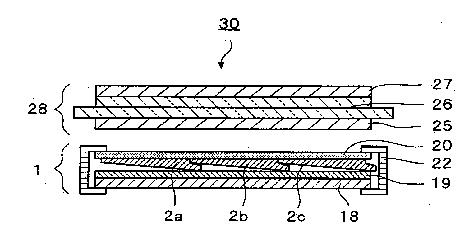
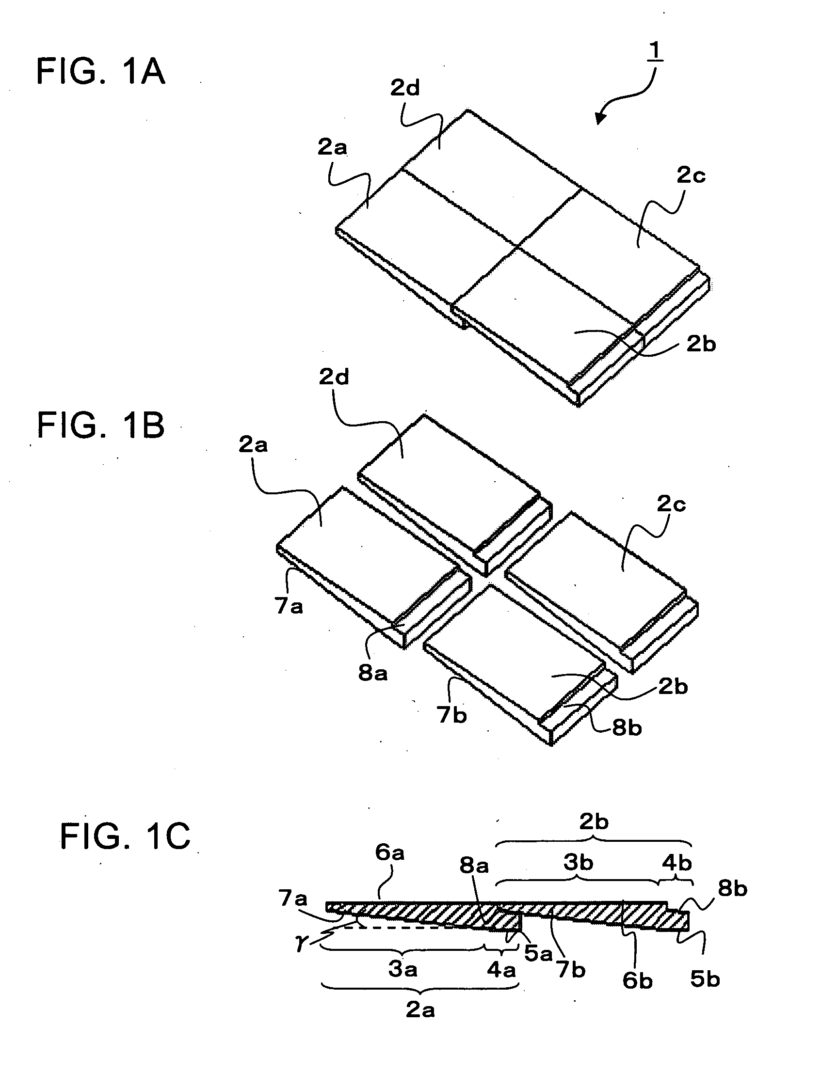
[0034]A lighting device according to Embodiment 1 of the present invention is described with reference to FIGS. 1A to 1C. FIG. 1A is a perspective view showing a lighting device including four surface light emitting plates. FIG. 1B is a perspective view showing a state in which the surface light emitting plates are separated from one another. FIG. 1C is a cross sectional view showing the four surface light emitting plates which are connected. As shown in FIG. 1A, a lighting device 1 includes four surface light emitting plates 2a, 2b, 2c, and 2d which are two-dimensionally arranged. As shown in FIG. 1B, the surface light emitting plates 2a to 2d can be separated from one another. The surface light emitting plates 2a to 2d fundamentally have the same shape and structure. As shown in FIG. 1C, the surface light emitting plate 2a includes a light guide portion 3a and a light source portion 4a which are integrally formed. Light emitted from the light source portion 4a passes through a reg...

embodiment 2

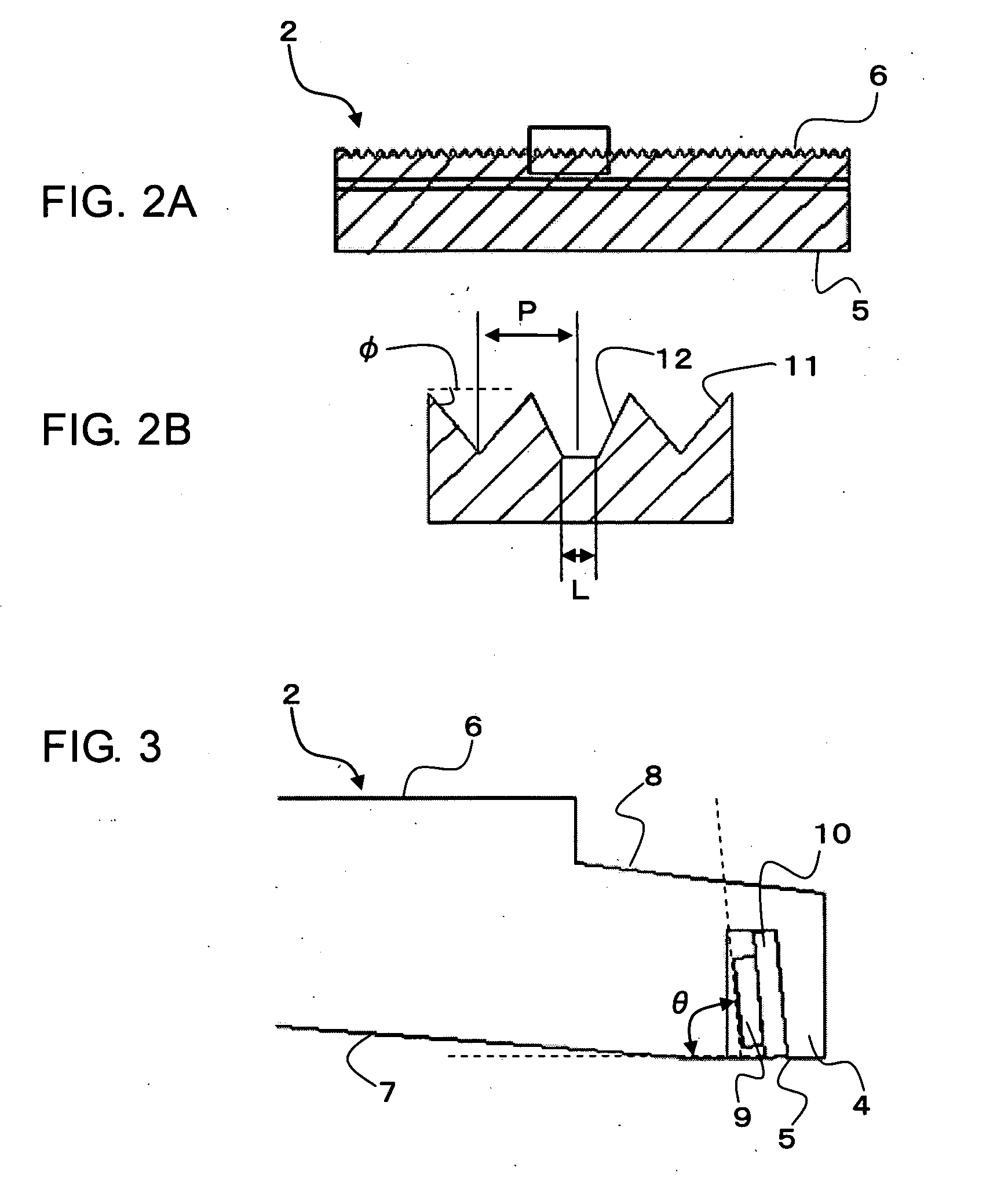
[0040]FIGS. 2A and 2B show a lighting device according to this embodiment of the present invention. FIG. 2A is a cross sectional view seen from a light incident portion side of a surface light emitting plate, and FIG. 2B is a partially enlarged view of FIG. 2A. As shown in FIG. 2A, a light emitting surface 6 of a surface light emitting plate 2 is subjected to light scattering treatment. The light scattering treatment may be surface roughening treatment such as a sand blast, or may be realized by forming unevenness on the surface by etching or printing. A light scattering surface or a prism surface may be formed simultaneously with the formation of a light guide portion 3 using injection molding. The light scattering surface may be formed on a light source portion bottom surface 5.

[0041]FIG. 2B is a partially enlarged cross sectional view showing the light emitting surface 6 of the surface light emitting plate 2, which shows a state in which V-grooves 11 and trapezoidal grooves 12 ar...

embodiment 3

[0043]FIG. 3 schematically shows a cross sectional structure of a lighting device according to Embodiment 3 of the present invention. The same parts or functions as those in the above-mentioned embodiments are denoted by the same reference symbols. As shown in FIG. 3, a light source 9 of the surface light emitting plate 2 is mounted on an FPC 10 and provided at an angle in order to prevent reflecting on the light emitting surface 6 of the surface light emitting plate 2. An angle θ formed between the light source portion bottom surface 5 and a surface of the light source 9 is preferably set to 85° to 90°. This reason is as follows. When the angle θ is equal to or smaller than 85°, light exits from only a light emitting surface in a region close to a light source portion 4. When the angle θ is equal to or larger than 90°, light exits from only a light emitting surface in a region far from the light source portion 4. Therefore, unevenness in brightness occurs.


PUM


Abstract

To provide a flat lighting device used for a liquid crystal display device and the like that can be made thin and lightweight and produced at low cost, the lighting device of the present invention includes a plurality of surface light emitting plates which are two-dimensionally arranged. Each of the plurality of surface light emitting plates includes a light guide portion and a light source portion provided in an end portion of the light guide portion. The light guide portion and the light source portion are integrally provided. The light source portion of a surface light emitting plate two-dimensionally overlaps with the light guide portion of another surface light emitting plate adjacent thereto, so light having a uniform intensity can be emitted above the plurality of surface light emitting plates.

Description

BACKGROUND OF THE INVENTION[0001]1. Field of the Invention[0002]The present invention relates to a flat backlight device used to illuminate a liquid crystal display panel from the rear surface side thereof, and a liquid crystal display device provided with the flat backlight device.[0003]2. Description of the Related Art[0004]Liquid crystal display devices are widely used. Each of the liquid crystal display devices includes a liquid crystal display panel and a flat backlight provided on the rear surface side thereof. In recent years, along with an increase in size of the liquid crystal display panel, the flat backlight becomes larger in size. The functions required for the large-size flat backlight are, for example, high and uniform intensity over the entire light emitting surface, being thin and lightweight, and a reduced manufacturing cost. In particular, along with increases in sizes of constituent members, the scale of an assembly line becomes larger to increase a capital invest...

Claims


Application Information

Patent Timeline
IPC IPC(8): G02F1/1335F21V5/02
CPCG02B6/0021G02B6/0038G02F1/133615G02B6/008G02B6/0046
Inventor TOMITA, NAOHIROKURIHARA, MAKOTOONO, MASASHI
Owner DAWNCREST IP LLC
Learn More