Diffractive optical element, optical system and optical apparatus

Inactive Publication Date: 2008-09-25
CANON KK
View PDF14 Cites 17 Cited by
  • Summary
  • Abstract
  • Description
  • Claims
  • Application Information

AI Technical Summary

Benefits of technology

[0020]The present invention provides a diffractive optical element achieving a high diffraction efficiency in a specific diffraction order (designed diffract

Problems solved by technology

However, in the case where the diffracted light of the diffraction orders other than the designed diffraction order exists with some degree of intensity, an image will be formed at a place different from that for the designed diffraction order, resulting in flare light generated in the optical system.
However, in the case of an optical system mounted to an optical apparatus such as a still camera and a video camera, even small amount of remaining flare light may be a problem when a high-intensity light source is present in an image-pickup area.
Meanwhile, in the case of the contacting two-layer DOE disclosed in the above Japanese Patent Laid-Open No. 2005-107298 and Japanese Pate

Method used


Image

  • Diffractive optical element, optical system and optical apparatus
  • Diffractive optical element, optical system and optical apparatus
  • Diffractive optical element, optical system and optical apparatus

Examples


Example

Embodiment 1

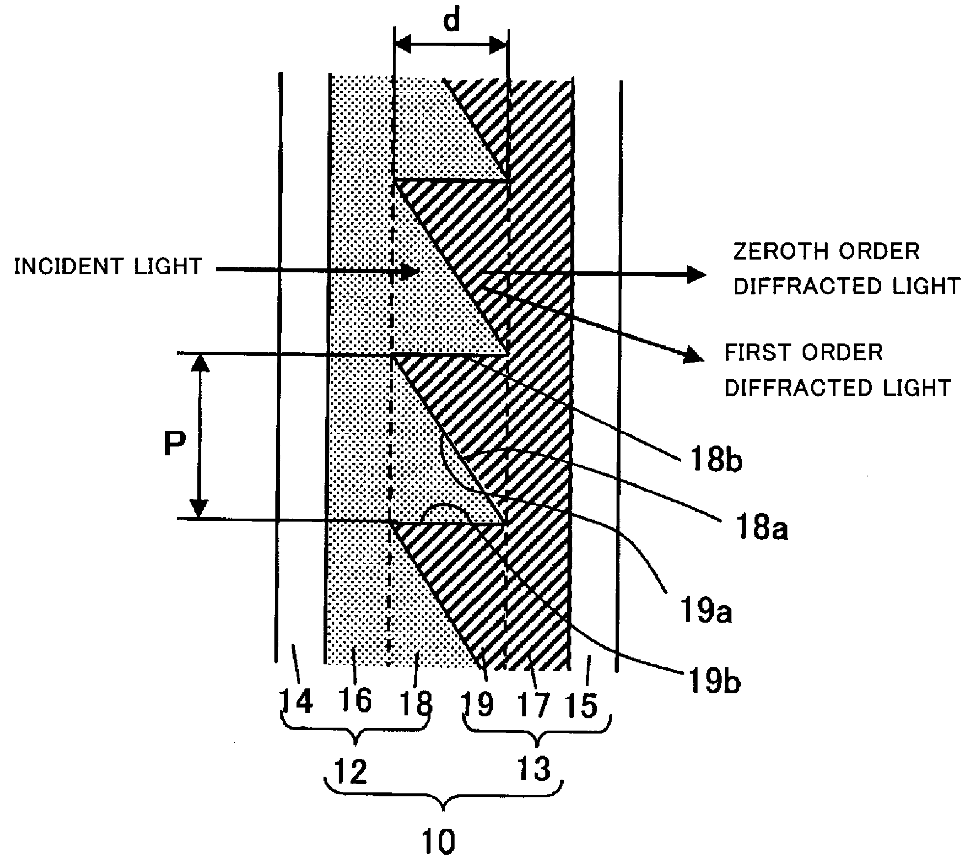
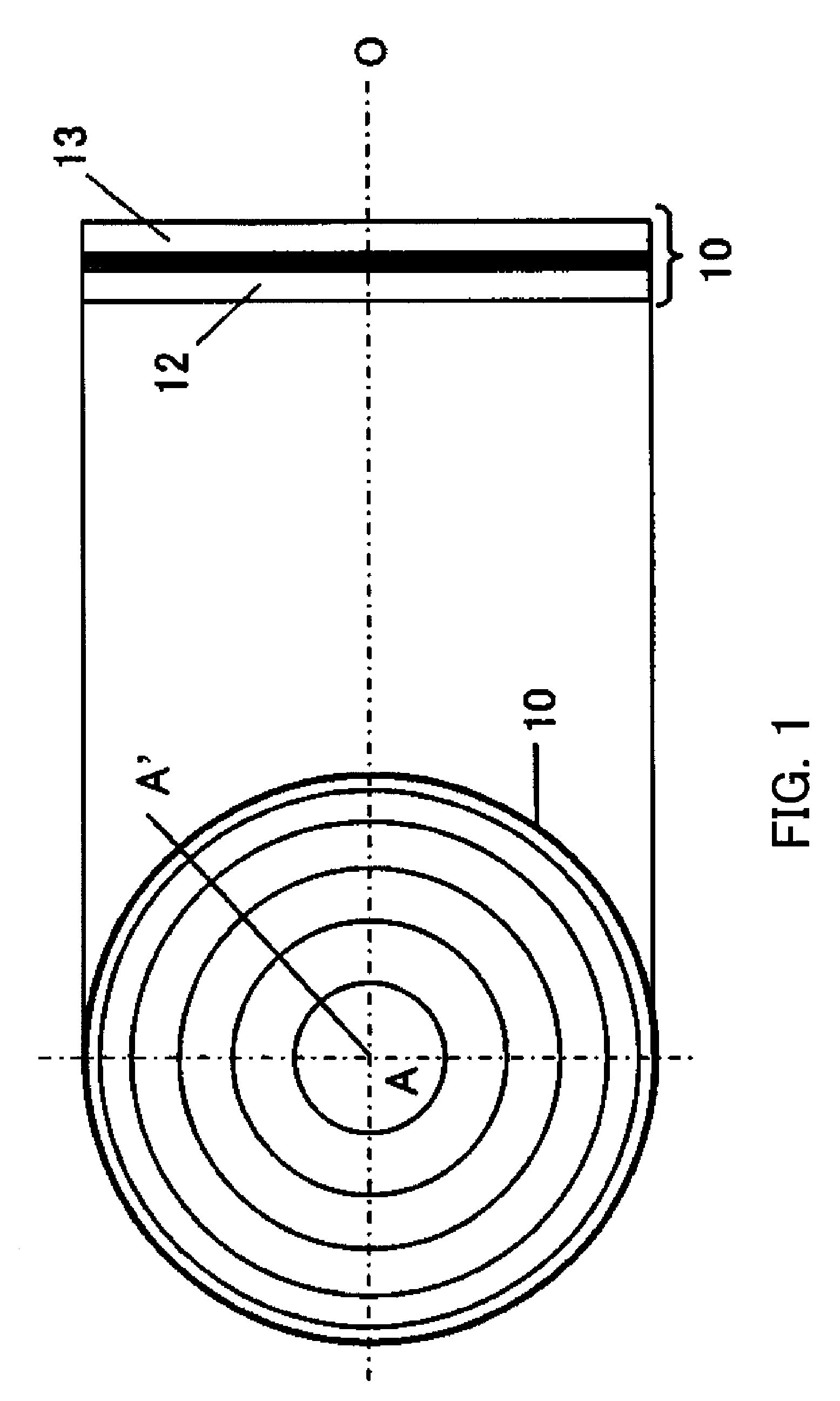
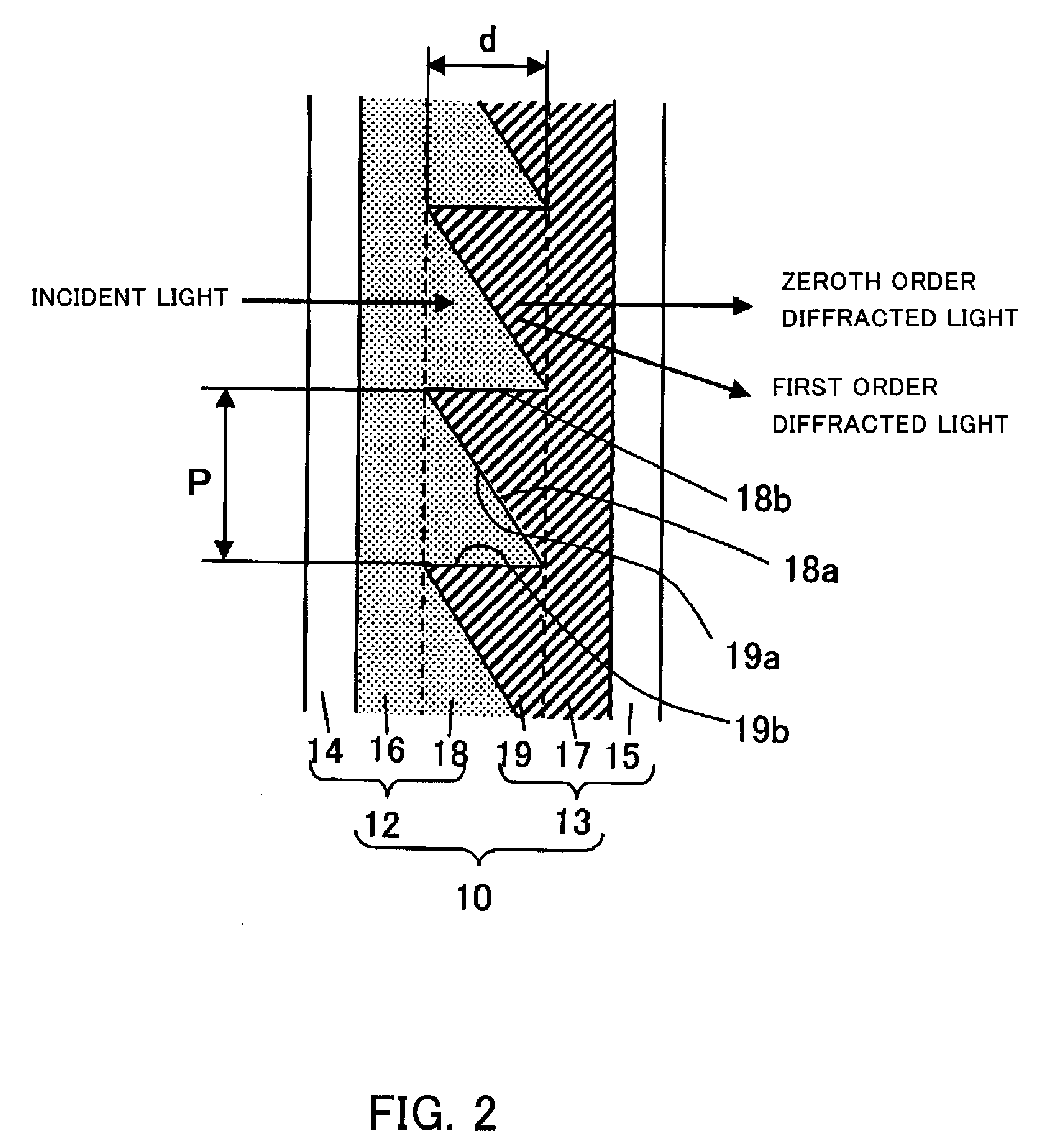
[0074]FIG. 1 is a front view (left drawing) as well as a side view (right drawing) of a diffractive optical element that is an embodiment (Embodiment 1) of the present invention. In FIG. 1, the character O represents a center axis of the diffractive optical element. FIG. 2 is a partially enlarged view showing the diffractive optical element of FIG. 1 in cross section taken along the line A-A′ in FIG. 1. It should be noted here that FIG. 2 is not drawn to scale in the grating depth direction.

[0075]As shown in these drawings, a diffractive optical element 10 includes a first element portion 12 and a second element portion 13. The first element portion 12 includes a first transparent substrate 14 and a first grating-forming layer made up of a grating base portion 16 provided on the first transparent substrate 14 and a first diffraction grating 18 integrally formed with the grating base portion 16. The second element portion 13 includes a second transparent substrate 15 and ...

Example

Embodiment 2

[0110]The following describes Embodiment 2 of the present invention. A diffractive optical element of this embodiment has basically the same configuration as that of Embodiment 1. That is, the element has the structure shown in FIGS. 1 and 2. Therefore, the same reference numerals will be assigned to the components common to those of Embodiment 1, their detailed explanations will be omitted and differences only will be focused on the following description.

[0111]In the diffractive optical element 10 of this embodiment, a first diffraction grating 18 shown in FIG. 2 is made of a mixed material (nd=1.611, νd=45.5) of acrylic resin and ZrO2 particles. A second diffraction grating 19 is made of a mixed material (nd=1.567, νd=21.7) of acrylic resin and ITO particles. The grating thickness d common to the first and second diffraction gratings 18 and 19 is 13.3 μm.

[0112]FIG. 5A shows the diffraction efficiency of the first order diffracted light in the diffractive optical elemen...

Example

Embodiment 3

[0114]The following describes Embodiment 3 of the present invention. A diffractive optical element of this embodiment has basically the same configuration as that of Embodiment 1. That is, the element has the structure shown in FIGS. 1 and 2. Therefore, the same reference numerals will be assigned to the components common to those of Embodiment 1, their detailed explanations will be omitted and differences only will be focused on the following description.

[0115]In the diffractive optical element 10 of this embodiment, a first diffraction grating 18 shown in FIG. 2 is made of a mixed material (nd=1.594, νd=58.0) of acrylic resin and Al2O3 particles. A second diffraction grating 19 is made of a mixed material (nd=1.519, νd=16.5) of fluorine resin and ITO particles. The grating thickness d common to the first and second diffraction gratings 18 and 19 is 7.8 μm.

[0116]FIG. 6A shows the diffraction efficiency of the first order diffracted light in the diffractive optical eleme...


PUM

PropertyMeasurementUnit
Temperatureaaaaaaaaaa
Thicknessaaaaaaaaaa
Efficiencyaaaaaaaaaa

Abstract

The diffractive optical element includes two diffraction gratings made of different materials and being in contact with each other at their grating surfaces. The materials satisfy the following conditions, and the second material is obtained by mixing a resin material with a particulate material satisfying the following conditions: nd1≧1.48, νd1≧40, (−1.665E−07×νd13+5.213E−05×νd12−5.656E×03×νd1+0.675)≦θg,F1≦(−1.665E−07×νd13+5.213E−05×νd12−5.656E−03×νd1+0.825), (−1.687E−07×νd13+5.702E−05×νd12−6.603E−03×νd1+1.400)≦θg,d 1≦(−1.687E−07×νd13+5.702E−05×νd12−6.603E−03×νd1+1.580), nd2≦1.6, νd2≦30, θg,F2≦(−1.665E−07×νd23+5.213E−05×νd22−5.656E−03×νd2+0.675 ), θg,d2≦(−1.687E−07×νd23+5.702E−05×νd22−6.603E−03×νd2+1.400 ), nd1-nd2≧0, ndb2≧1.70, νdb2≦20. The element achieves a high diffraction efficiency in a specific diffraction order over a wide wavelength range.

Description

BACKGROUND OF THE INVENTION[0001]The present invention relates to a diffractive optical element for use in an optical system and an optical apparatus, and more particularly relates to a diffractive optical element configured so that diffraction gratings made of two materials are in contact with each other.[0002]There is a method for reducing chromatic aberration by a combination of glass materials. On the other hand, other methods are disclosed for reducing chromatic aberration in SPIE Vol.1354 International Lens Design Conference (1990), Japanese Patent Laid-Open No. 4(1992)-213421, Japanese Patent Laid-Open No. 6(1994)-324262 and U.S. Pat. No. 5,044,706, which provide a diffractive optical element (hereinafter, this may be called a diffraction grating) having a diffraction function at a lens surface or as a part of an optical system. Such a method utilizes a physical phenomenon that chromatic aberration occurs in opposite directions between at a refractive surface and at a diffrac...

Claims


Application Information

Patent Timeline
IPC IPC(8): G02B5/18
CPCG02B1/04G02B5/1823G02B27/4272G02B27/0037G02B27/4211G02B5/1866
Inventor YASUI, HIROTO
Owner CANON KK
Why Eureka
Try Eureka