Voice coil motors and magnetic circuits therefor

US20080231996A1Inactive Publication Date: 2008-09-25SHIN ETSU CHEM IND CO LTD

Image

  • Voice coil motors and magnetic circuits therefor
  • Voice coil motors and magnetic circuits therefor
  • Voice coil motors and magnetic circuits therefor

Examples


example 1

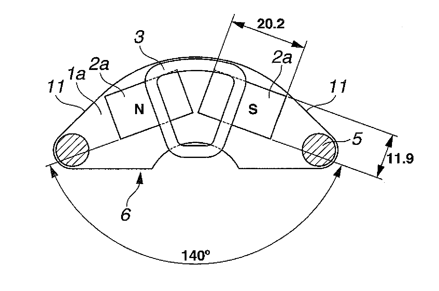
[0036]A Nd—Fe—B sintered magnetizable block (N48M by Shin-Etsu Chemical Co., Ltd.) was machined into rectangular prisms of 20.2 mm×11.9 mm×6 mm. Two pieces in an angle array were adhesively attached to a yoke of carbon steel having a thickness of 5 mm and then magnetized in a thickness direction by means of a magnetizer, so that the angle-arrayed magnet pieces produced alternate magnetic poles along the yoke. In this way, a magnetic circuit was constructed. The angle included between the longitudinal axes of two magnet pieces was 140°.

[0037]Two yokes (or magnetic circuits) were fixedly coupled by posts to define a space of 10 mm between the magnets. An arm having a moving coil of copper wire wound thereon was inserted into the space, constructing a VCM as shown in FIG. 4. The torque of VCM was measured with the results shown in FIG. 8.

example 2

[0038]A Nd—Fe—B sintered magnetizable block (N48M by Shin-Etsu Chemical Co., Ltd.) was machined into parallelepiped prisms of 19.5 mm×11.9 mm×6 mm. Two pieces in an angle array were adhesively attached to a yoke of carbon steel having a thickness of 5 mm and then magnetized in a thickness direction by means of a magnetizer, so that the angle-arrayed magnet pieces produced alternate magnetic poles along the yoke. In this way, a magnetic circuit was constructed. The angle included between the longitudinal axes of two magnet pieces was 140°.

[0039]Two yokes (or magnetic circuits) were fixedly coupled by posts to define a space of 10 mm between the magnets. An arm having a moving coil of copper wire wound thereon was inserted into the space, constructing a VCM as shown in FIG. 5. The torque of VCM was measured with the results shown in FIG. 8.


PUM


Abstract

Two magnet pieces of rectangular prism or parallelepiped prism shape are disposed on a yoke in an angle array to construct a magnetic circuit for a voice coil motor. The magnetic circuits facilitate positioning and holding of a moving coil, and the voice coil motor is improved in positioning precision of a magnetic head.

Description

CROSS-REFERENCE TO RELATED APPLICATION[0001]This non-provisional application claims priority under 35 U.S.C. §119(a) on Patent Application No. 2007-072828 filed in Japan on Mar. 20, 2007, respectively, the entire contents of which are hereby incorporated by reference.TECHNICAL FIELD[0002]This invention relates to voice coil motors for head positioning in magnetic disk units, and magnetic circuits for use therein.BACKGROUND OF THE INVENTION[0003]In general, a hard disk unit includes a medium having a magnetic recording film deposited thereon, a spindle motor for rotating the medium at a predetermined rotational speed, a magnetic head for writing and reading information data, a voice coil motor (VCM) for driving the magnetic head, a controller and the like. The recent drastic price competition among manufacturers imposes a demand for further cost reduction on voice coil motors as well.[0004]Referring to FIG. 1, a voice coil motor 10 includes magnetic material yokes 1, 1 and magnets (p...

Claims


Application Information

Patent Timeline
25 Sep 2008
Publication
US20080231996A1
IPC
G11B5/56
CPC
G11B5/5521; G11B21/02; H02K33/18
Inventors
YAMADA, HIROYUKI; KATO, DAIKI