High linearity, low noise figure, front end circuit with fine step gain control

a gain control and linearity technology, applied in the field of gain control circuits, can solve the problems of limiting the bandwidth of the circuit, limiting the value of the resistor to be quite small, and the expense of inferior linearity at high signal levels

Active Publication Date: 2008-09-25
ATMEL CORP
View PDF14 Cites 49 Cited by
  • Summary
  • Abstract
  • Description
  • Claims
  • Application Information

AI Technical Summary

Problems solved by technology

However, the gain control is continuous as in a baseband variable gain amplifier (VGA), which comes at the expense of inferior linearity at high signal levels.
Furthermore, matching requirements at the input often constrain the values of these resistors to be quite small.
The repercussions are large transistor switches, which tend to dramatically limit the bandwidth of the circuit.

Method used


Image

  • High linearity, low noise figure, front end circuit with fine step gain control
  • High linearity, low noise figure, front end circuit with fine step gain control
  • High linearity, low noise figure, front end circuit with fine step gain control

Examples


Embodiment Construction

[0023]The embodiments herein and the various features and advantageous details thereof are explained more fully with reference to the non-limiting embodiments that are illustrated in the accompanying drawings and detailed in the following description. Descriptions of well-known components and processing techniques are omitted so as to not unnecessarily obscure the embodiments herein. The examples used herein are intended merely to facilitate an understanding of ways in which the embodiments herein may be practiced and to further enable those of skill in the art to practice the embodiments herein. Accordingly, the examples should not be construed as limiting the scope of the embodiments herein.

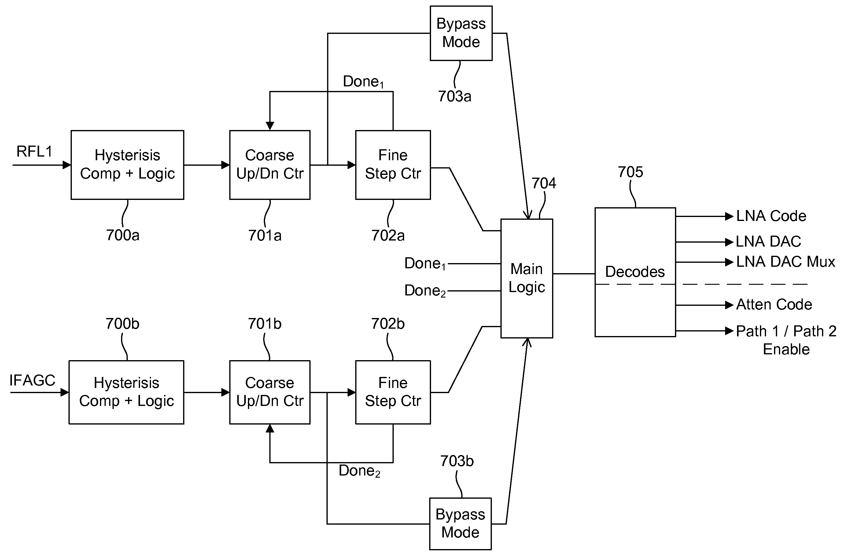
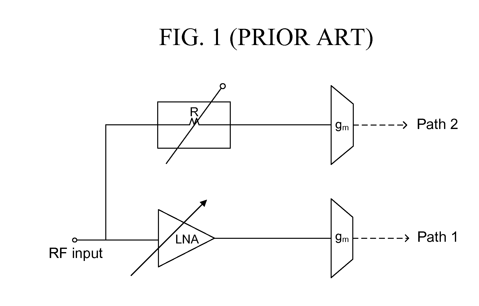
[0024]As mentioned, there remains a need for a highly linear, low noise figure front end circuit that can provide fine step gain control. The embodiments herein achieve this by providing a front end circuit that allows a switch between two RF paths to improve linearity at high signal power. The...


PUM


Abstract

A system, method, and electrical circuit comprises a LNA signal line path comprising a LNA and a first signal mixer operatively connected to the LNA. The circuit further comprises an attenuator signal line path comprising an attenuator and a second signal mixer operatively connected to the attenuator; a radio frequency (RF) power detector operatively connected to an output of each of the LNA and the attenuator, wherein the RF power detector is adapted to vary a front end power gain of the electrical circuit; and logic circuitry operatively connected to the RF power detector, wherein the logic circuitry is adapted to (i) select transmission of a signal through only one of the LNA signal line path or the attenuator signal line path, and (ii) output the selected signal.

Description

BACKGROUND[0001]1. Technical Field[0002]The embodiments herein generally relate to gain control circuits, and, more particularly, to circuits used for improving the dynamic range with low noise figure at sensitivity and improve step gain in communication devices.[0003]2. Description of the Related Art[0004]As shown in FIG. 1, the tuner input goes to both a low noise amplifier (LNA) input and an attenuator input creating two separate signal paths (both paths have variable gain control). However, the gain control is continuous as in a baseband variable gain amplifier (VGA), which comes at the expense of inferior linearity at high signal levels. Moreover, fine stepping the gain allows for easier and smarter logic processing deciding how to step the front end gain.[0005]Conventionally, the attenuators have taken the form of R-2R ladders as shown in FIG. 2, which typically require switches both in series with the signal path as well as in a shunt configuration. Furthermore, matching requ...

Claims


Application Information

Patent Timeline
Patent Type & Authority Applications(United States)
IPC IPC(8): H04B1/06H03K17/082
CPCH03K17/005H04B1/18H03K17/6871
Inventor SIVASUBRAMANIAM, JANAKAN
Owner ATMEL CORP
Why Eureka
Try Eureka