Vertebral Stabilizer

a stabilizer and vertebral technology, applied in the field of can solve the problems of severe back pain and nerve damag

Active Publication Date: 2008-09-25
WARSAW ORTHODEPIC
View PDF56 Cites 138 Cited by
  • Summary
  • Abstract
  • Description
  • Claims
  • Application Information

AI Technical Summary

Benefits of technology

[0002]In accordance with one aspect of the present disclosure, an implant for stabilizing bony structures is presented. The implant includes a first end, a second end, and an extendable member connected to the first end and the second end. The extendable member is sized to traverse a spac...

Problems solved by technology

Severe back pain and nerve damage may be caused by injured, ...

Method used


Image

  • Vertebral Stabilizer
  • Vertebral Stabilizer
  • Vertebral Stabilizer

Examples


Embodiment Construction

[0014]The present disclosure relates generally to the field of orthopedic surgery, and more particularly to systems and methods for stabilizing a spinal joint. For the purposes of promoting an understanding of the principles of the invention, reference will now be made to embodiments or examples illustrated in the drawings, and specific language will be used to describe the same. It will nevertheless be understood that no limitation of the scope of the invention is thereby intended. Any alteration and further modifications in the described embodiments, and any further applications of the principles of the invention as described herein are contemplated as would normally occur to one skilled in the art to which the disclosure relates.

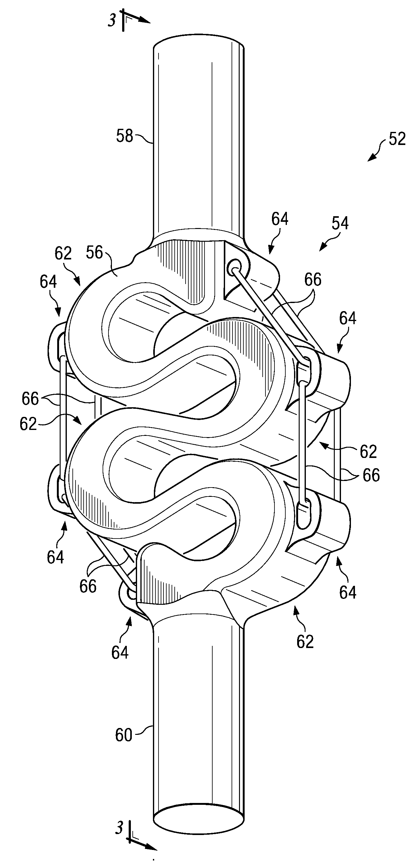
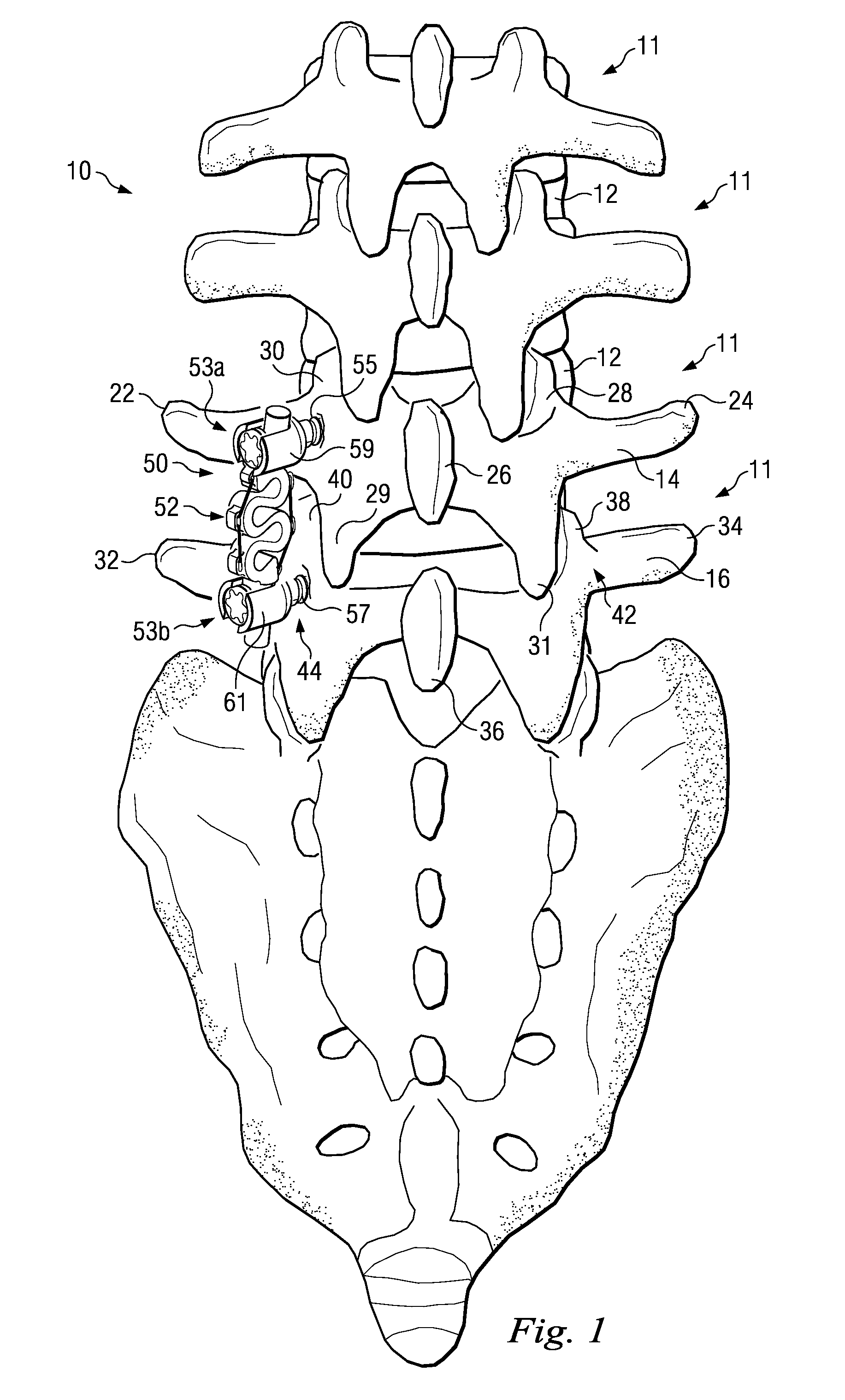
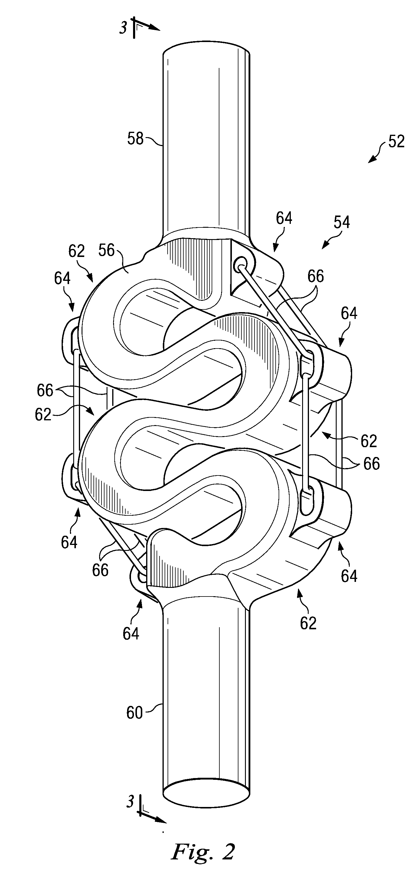
[0015]Referring to FIG. 1, the numeral 10 refers to a spinal column having a series of vertebral joints 11, each including an intervertebral disc 12. One of the vertebral joints 11 will be described further with reference to adjacent vertebrae 14, 16. The...


PUM


Abstract

A bio-compatible stabilization system includes one or more inserters and a connector for traversing a space between one or more bony structures. The stabilization system is designed to reduce or eliminate stress shielding effects while functioning as a tension band. The connector includes an extendable member and an over-extension limiter that limits extension of the extendable member.

Description

BACKGROUND[0001]Severe back pain and nerve damage may be caused by injured, degraded, or diseased spinal joints and particularly, spinal discs. Current methods of treating these damaged spinal discs may include vertebral fusion, nucleus replacements, or motion preservation disc prostheses. Disc deterioration and other spinal deterioration may cause spinal stenosis, a narrowing of the spinal canal and / or the intervertebral foramen, that causes pinching of the spinal cord and associated nerves. Current methods of treating spinal stenosis include laminectomy or facet resection. Alternative and potentially less invasive options are needed to provide spinal pain relief.SUMMARY[0002]In accordance with one aspect of the present disclosure, an implant for stabilizing bony structures is presented. The implant includes a first end, a second end, and an extendable member connected to the first end and the second end. The extendable member is sized to traverse a space between at least two bony ...

Claims


Application Information

Patent Timeline
IPC IPC(8): A61B17/70A61B17/58
CPCA61B17/7026A61B17/7011
Inventor TRIEU, HAI H.CARLS, THOMASDEWEY, JONATHAN
Owner WARSAW ORTHODEPIC
Why Eureka
Try Eureka