Techniques for generating a trace stream for a data processing apparatus
- Summary
- Abstract
- Description
- Claims
- Application Information
AI Technical Summary
Benefits of technology
Problems solved by technology
Method used
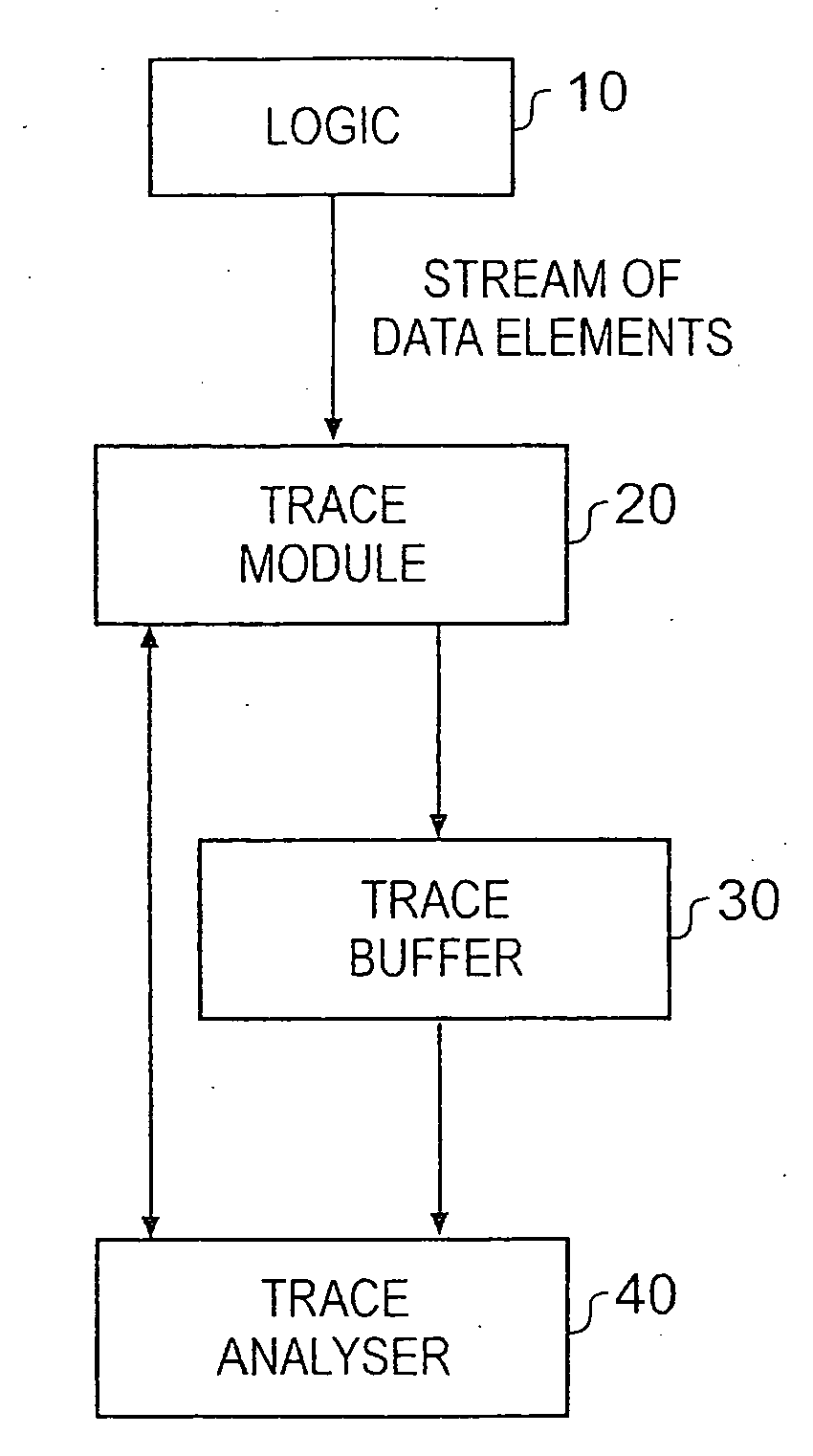
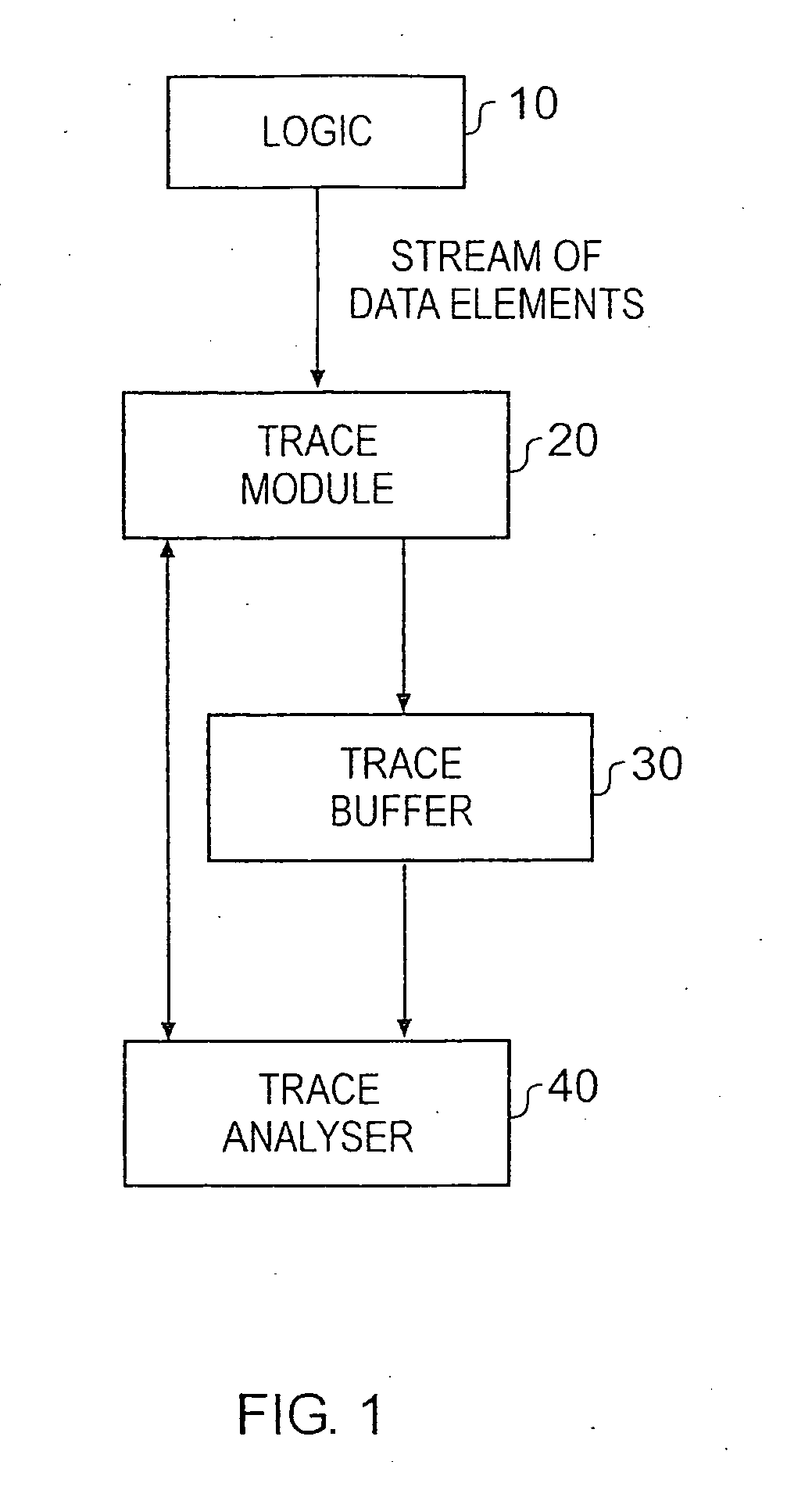
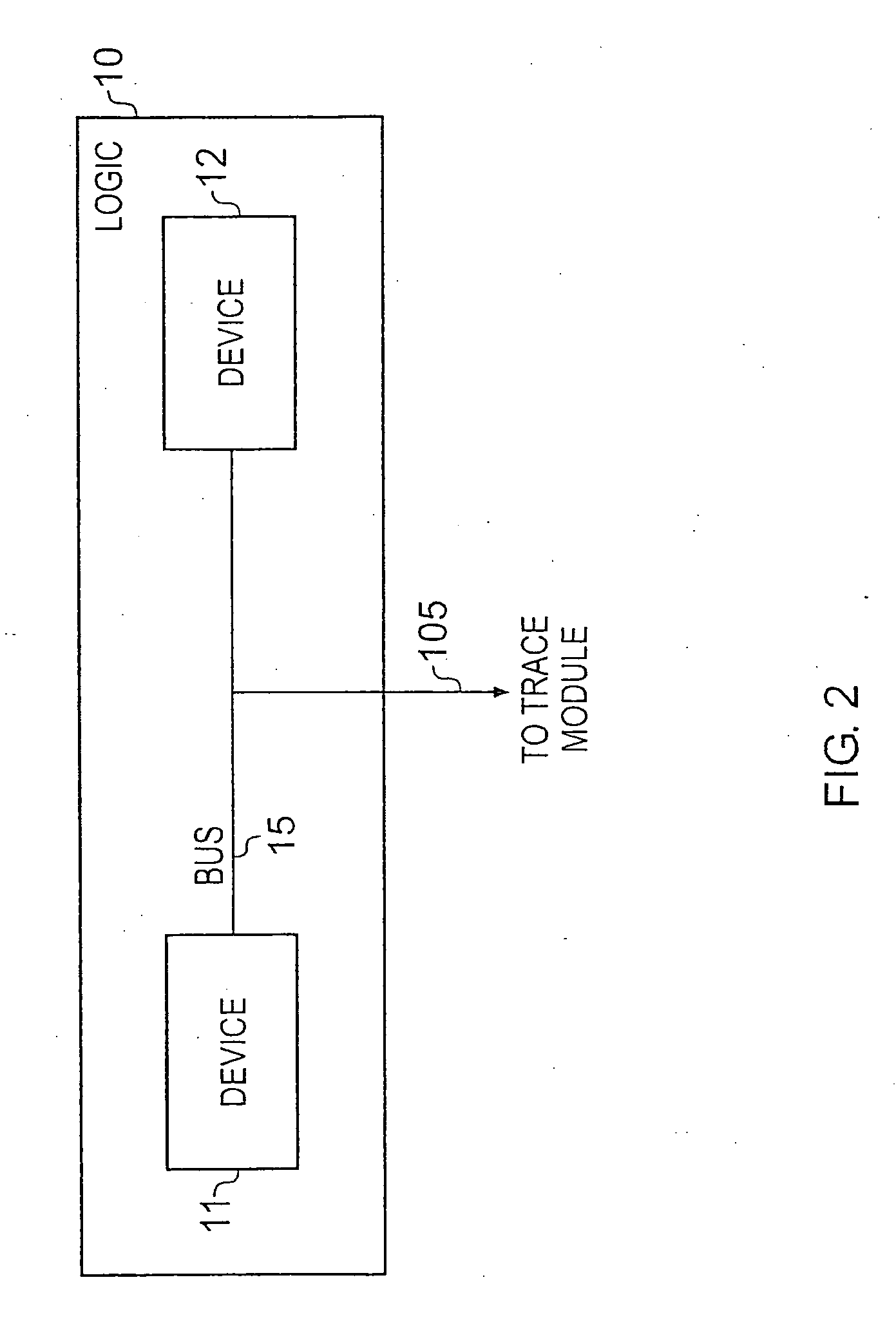
Image

Examples
example 1a
[0094]Table 4 below illustrates this example. In this example events A and B are events of interest and the cycle count is reset at events of interest.
TABLE 4Trace withoutTrace withCyclestimingtiming0W4Event AEvent A812W1620W2426Event BEvent B283234W
[0095]Between 16 and 24 cycles have passed between Events A and B.
example 1b
[0096]Table 5 below illustrates this example. In this example the cycle count is NOT reset at events of interest.
TABLE 5Trace withoutTrace withCyclestimingtiming0W4Event AEvent A8W1216W2024W26Event BEvent B2832W34
[0097]Between 16 and 32 cycles have passed between Events A and B. This has larger error-bars at each event of interest than does Example 1a, but is a true heartbeat.
example 2
[0098]Table 6 below illustrates this example. Each event of interest includes a cycle count referring to the number of cycles since the last indicator. The cycle count IS reset at the event of interest (this is the optional path on FIG. 5).
TABLE 6Trace withoutTrace withCyclestimingtiming0W4Event A4 cycles since lastindicator + Event A12W1620W2426Event B6 cycles since lastindicator + Event B283234W
[0099]Event A occurs 4 cycles after cycle 0. Event B occurs 22 cycles ((2*8)+6) after Event A.
PUM
 Abstract
Description
Claims
Application Information
 - Generate Ideas
- Intellectual Property
- Life Sciences
- Materials
- Tech Scout
- Unparalleled Data Quality
- Higher Quality Content
- 60% Fewer Hallucinations
Browse by: Latest US Patents, China's latest patents, Technical Efficacy Thesaurus, Application Domain, Technology Topic, Popular Technical Reports.
© 2025 PatSnap. All rights reserved.Legal|Privacy policy|Modern Slavery Act Transparency Statement|Sitemap|About US| Contact US: help@patsnap.com