
Coupling

a technology of coupling and splint, applied in the field of coupling, can solve the problems of inability to provide substantial benefits to the structural integrity, damage to the surrounding environment, and all traditional hinging methods are limited in both their application and application, and achieve the effect of high load bearing capacity and strong impact resistan

Inactive Publication Date: 2008-10-02
ACIN 1
View PDF7 Cites 5 Cited by
  • Summary
  • Abstract
  • Description
  • Claims
  • Application Information

AI Technical Summary

Benefits of technology

"The patent describes a coupling that connects two objects together. The coupling has a coupling arm with an attachment portion that can be attached to the first object and an anchor portion that can be retained within a receptacle on the second object. The coupling arm can be moved between a closed position and an open position. The interior of the receptacle can hold the anchor portion when the coupling arm is closed. The coupling segments can be attached with lynch pins and the receptacle can be incorporated within the second object. The technical effects of this coupling include high load bearing capacity, impact resistance, and strength."

Problems solved by technology

Hinging devices have therefore always been an ancillary device to construction without the ability to provide substantial benefits to the structural integrity of something as large as a building.
All traditional hinging methods are limited in both their application and ability to allow two surfaces to move in relation to each other, and if not fit for purpose cause major damage to their surrounding environment.

Method used


Image

  • Coupling
  • Coupling
  • Coupling

Examples


Embodiment Construction

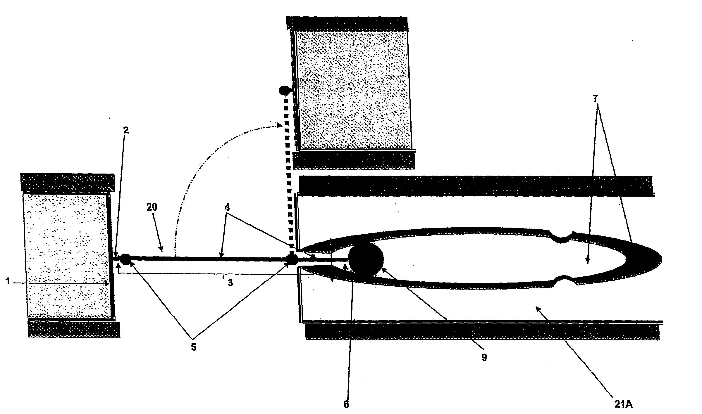
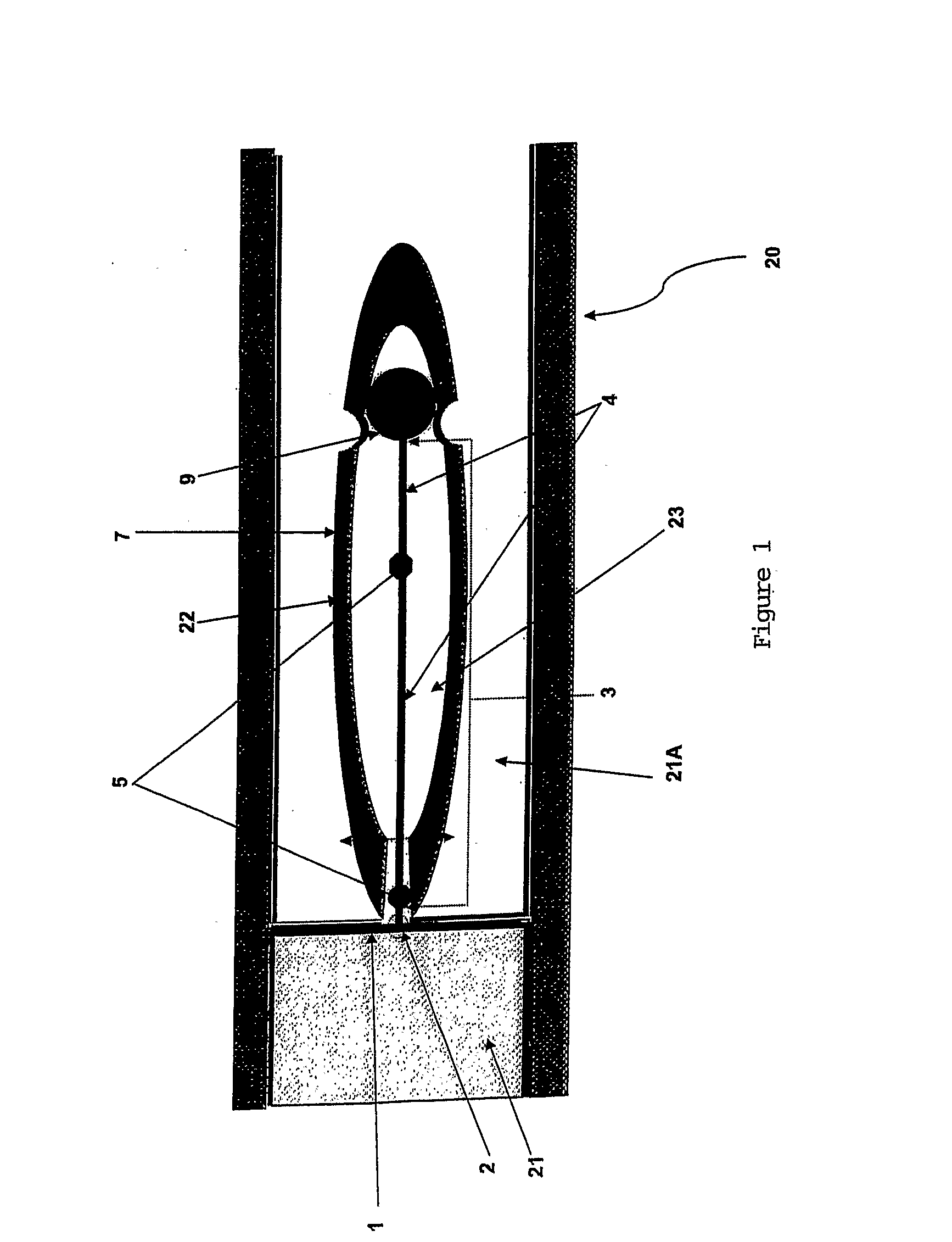
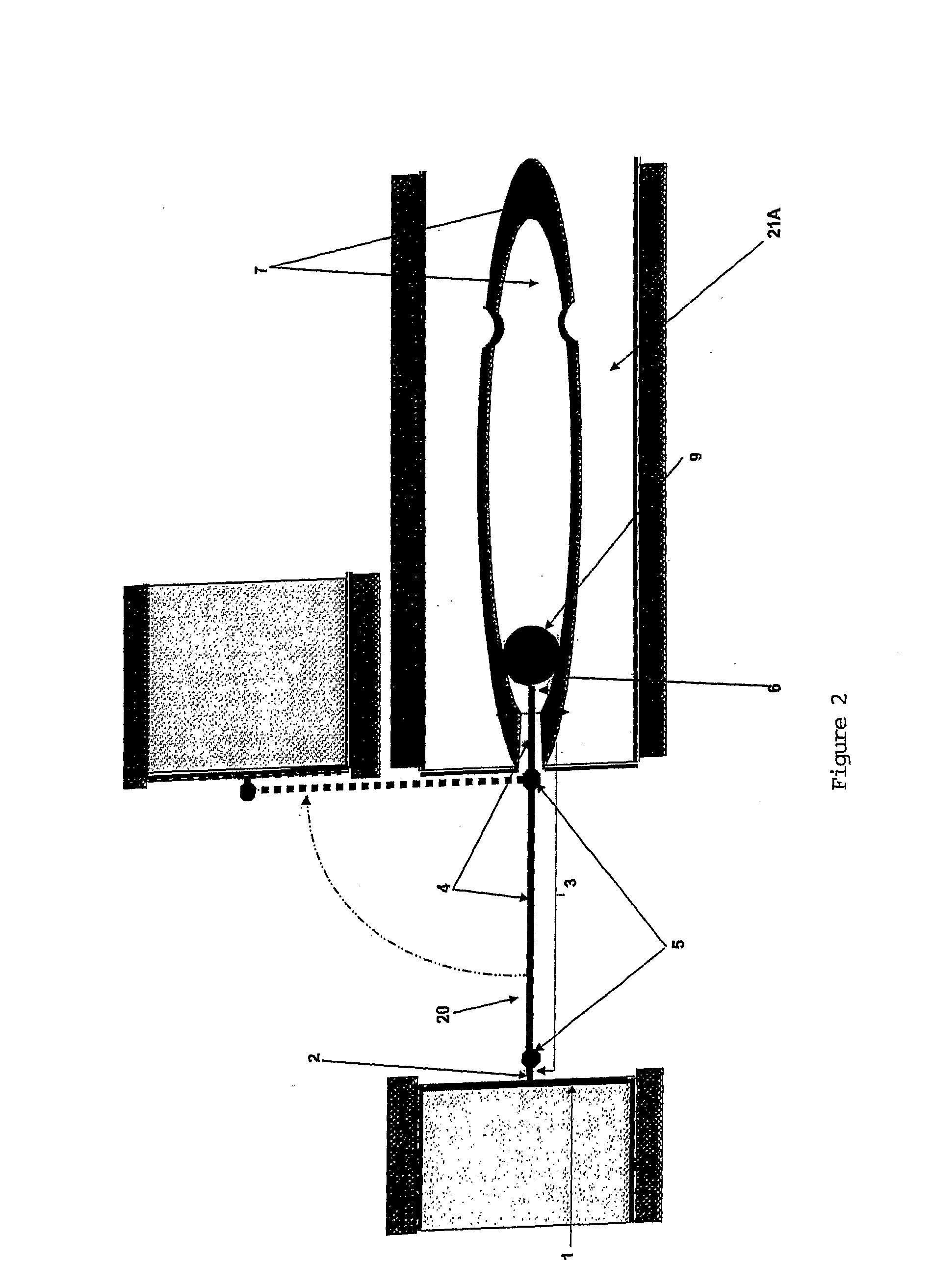
[0026]Referring to the figures, disclosed is a coupling 20 comprising an attachment means 1 which is affixed to an article 21. The attachment means 1 is a plate composed of resilient or non-resilient material or a combination of materials such as moulded, pressed, stamped or extruded metals, laminated metals or high-tensile plastics.

[0027]The coupling 20 includes a coupling arm 3 which is anchored to the attachment means 1 at anchor point 2. The coupling arm 3 is anchored to the attachment means 1 by a method dependent on the material(s) used to construct the attachment means 1 and forms part of the attachment means structure.

[0028]The coupling arm 3 comprises two coupling segments 4. The coupling segments 4 are composed of resilient or non-resilient material or a combination of materials such as moulded, pressed, stamped or extruded metals, laminated metals or hi-tensile plastics. The coupling segments 4 are interconnected by means of lynch pin inserts 5 or any other hinged connect...


PUM


Abstract

Disclosed is a coupling, comprising a coupling arm, the coupling arm having an attachment portion adapted to be affixed with a first article, and an anchor portion. The coupling further comprises a receptacle adapted to be affixed with a second article, the receptacle comprising one or more walls defining an interior cavity, adapted to retain at least the anchor portion of the coupling arm. The receptacle further includes an opening adapted to allow the coupling arm to extend therethrough, wherein the attachment portion of the coupling arm is moveable with respect to the opening.

Description

FIELD OF THE DISCLOSURE[0001]The disclosure relates to a coupling for walls, doors, containers or other building or construction elements.BACKGROUND TO THE DISCLOSURE[0002]Traditional methods for hinging walls, doors, container lids and other construction or building materials are reliant on a dual base plate construction fitted together and connected by a single lynch pin fed through aligned apertures to form the coupling pivot point. The coupling is then affixed by each coupling base plate to independent surfaces (for example door and door mount) to both connect the two independent surfaces and allow one to move in relation to the other.[0003]Many innovations have evolved in recent times in relation to coupling devices dependant on the application requirements, however the basic premise of the coupling's ability to allow two independent surfaces to be connected by the coupling and have a single point of articulation has not changed in the last one thousand years. Hinging devices h...

Claims


Application Information

Patent Timeline
Patent Type & Authority Applications(United States)
IPC IPC(8): E05D3/18E05D7/04E05D3/02
CPCE05D3/06E05D3/12E05D3/18E05D5/08E05D9/00Y10T16/5472E05D2007/0476E05Y2600/41E05Y2900/20E05Y2900/538E05D15/58
Inventor MILLER, ANNETTE LOUISE
Owner ACIN 1
Learn More