Compliant banding system

a banding system and conforming technology, applied in the field of fasteners, can solve the problems of reducing the life span of cylindrical structures, brittleness and inflexibility, gses have fractured, cracked and broken away from cylindrical structures, etc., and achieve the effect of effectively preventing the dislodgment of the straps and prolonging the length of the channel

Inactive Publication Date: 2008-10-02
VIV SUPPRESSION
View PDF10 Cites 32 Cited by
  • Summary
  • Abstract
  • Description
  • Claims
  • Application Information

AI Technical Summary

Benefits of technology

[0022]The compliant banding system of the present invention comprises a compliant member, an attached channel member and a strap extending through the channel, all constructed to extend circumferentially around a strake or fairing collar. The strap is moveable within the channel and may be attached to itself to define a fixed circumference. Opposing first and second retainer segments extend the length of the channel member. The retainer segments partially enclose the strap within the channel of the channel member effectively preventing dislodgment of the strap. The compliant member is positioned adaxially and is constructed of a flexible material such as polyether based polyurethane. Accordingly, the compliant member is flexible within determined ranges intermediate the underlying structure and the fixed-circumference strap.
[0023]Th

Problems solved by technology

VIVs have been shown to greatly reduce the life span of cylindrical structures.
Although epoxies provide excellent insulating characteristics, they are also stiff, brittle and inflexible.
GSEs have fractured, cracked and broken away from the cylindrical structures they were insulating due to their brittleness.
These occurrences permit desirable heat to escape from the cylindrical structures contents typically causing a slow down in production.
However, as a natural byproduct of this desired increase in flexibility the naturally occurring hydrostatic pressure exerted by the water, that has no discernible effect on the stiff, inflexible epoxy resin, actually compresses the GSPU at great depths causing a decrease in the outer diameter.
Although this procedure is sufficient when GSE is used as the insulator, it is impractical when utilizing the more desirable GSPU insulation.
The strakes are then free to rotate along with the current, slide along the cylindrical structure, and/or become inter-tangled with other strakes, all of which are not desirable.
Ris

Method used


Image

  • Compliant banding system
  • Compliant banding system
  • Compliant banding system

Examples


Embodiment Construction

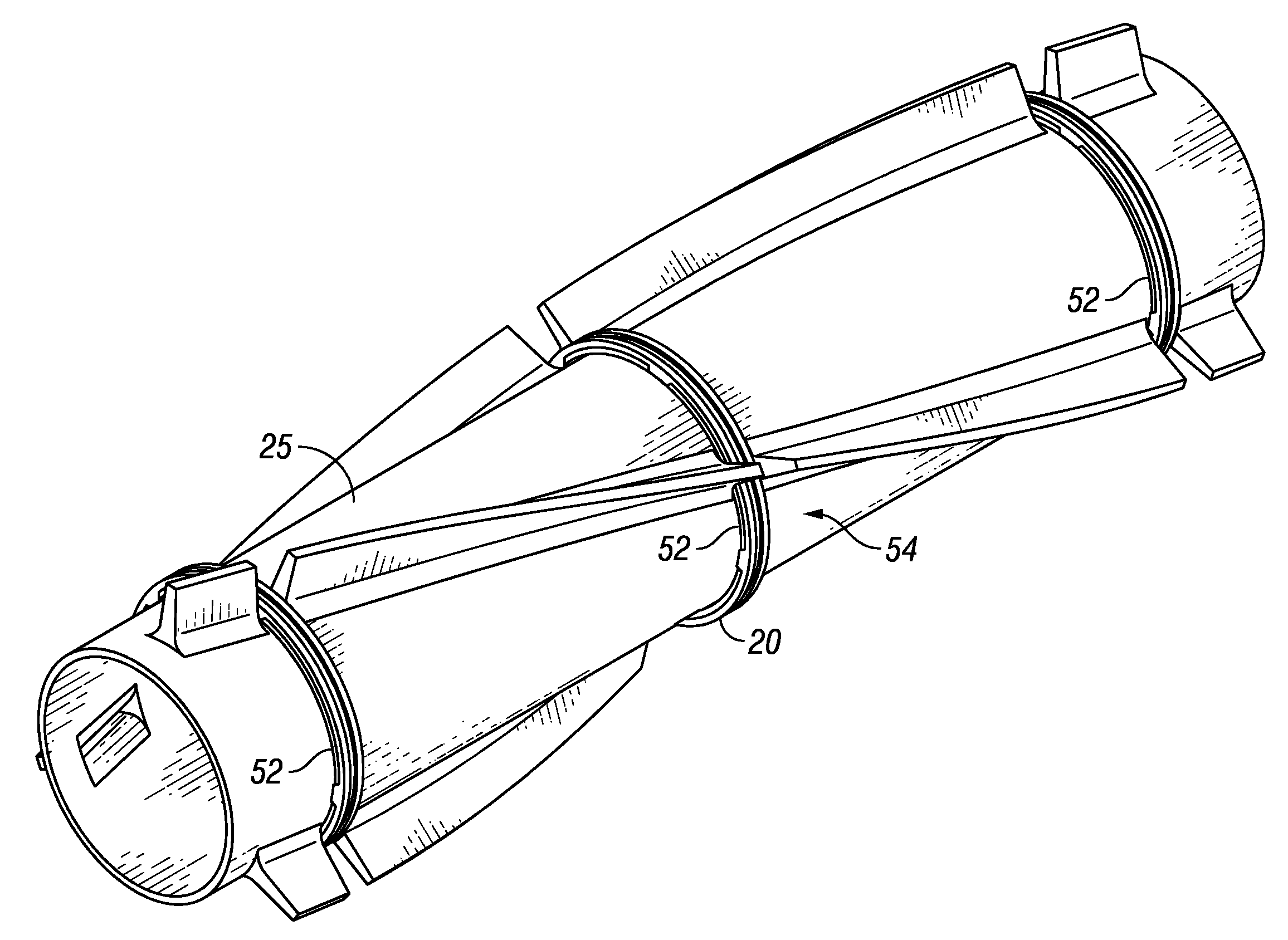
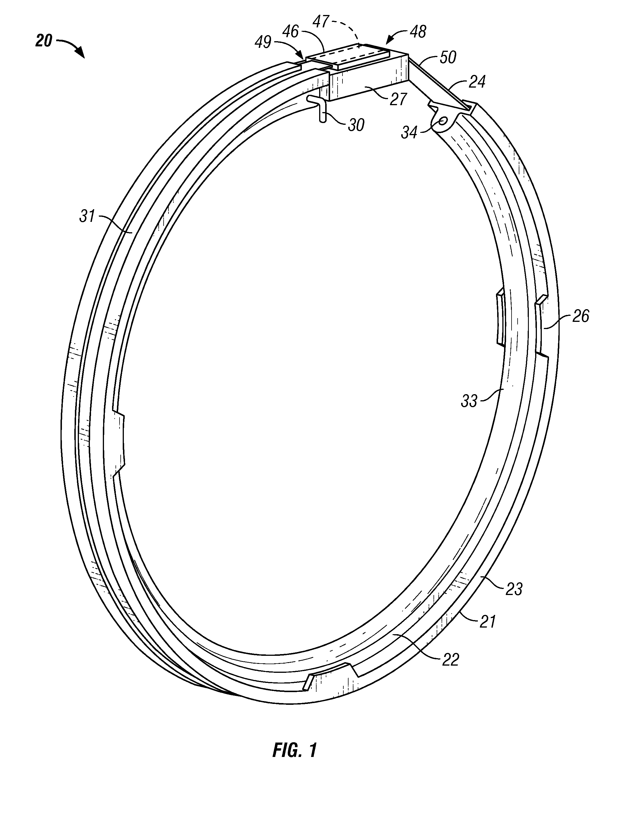
[0037]The invention and its advantages are best understood by referring to the drawings, like numerals being used for like and corresponding parts of the various drawings. FIGS. 1-4 show the preferred embodiment of the compliant banding system 20 of the present invention.

[0038]Referring to FIG. 1, compliant banding system 20 includes compliant band 21 comprising compliant member 22 attached to channel member 23. Channel member 23 defines channel 31. A strap 24 extending through channel 31. Solid spacer 27 is removably attached to compliant member 22 by sacrificial pin 30. Compression indicators 26 are provided on channel member 23.

[0039]Compliant band 21 is constructed to extend circumferentially around a structure such as a strake or fairing collar (not shown).

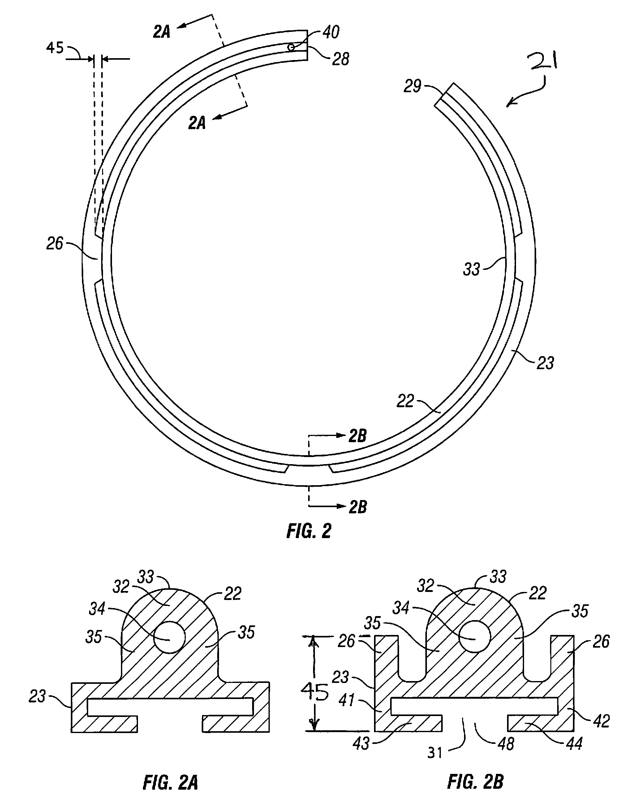
[0040]In an exemplary embodiment, interior cavity 34 extends through compliant band 21. Interior cavity 34 enhances flexibility of compliant band 21.

[0041]Referring to FIG. 2, compliant member 22 is positioned adaxially. FIG....


PUM


Abstract

The present invention discloses a compliant banding system for use in a marine environment comprising a flexible compliant member and an abaxial relatively rigid strap, both constructed to extend circumferentially around an underlying structure such as a strake or fairing collar. The strap maintains a fixed circumference while the compliant member flexes intermediate the strap and an underlying.

Description

CROSS-REFERENCE TO RELATED APPLICATIONS[0001]None.STATEMENT REGARDING FEDERALLY SPONSORED RESEARCH OR DEVELOPMENT[0002]Not Applicable.BACKGROUND OF THE INVENTION[0003]1. Field of the Invention[0004]The present invention relates to fasteners in general, and more particularly to a banding system for use in securely attaching strakes and fairings onto cylindrical structures used in the offshore industry.[0005]2. Description of the Related Art[0006]Vortex-induced vibrations (VIVs) are a concern in the offshore industry where elongated structures, such as tension leg platforms, spars, etc., are utilized. VIVs may be generated when fluid flows past an elongated structure. As current flows past a structure, friction at the structure / fluid interface slows proximal fluid flow. Vortex eddies result from the differential fluid velocity of the proximal and distal fluid flow.[0007]Floating structures possess long, cylindrical components, such as steel catenary risers (SCRs), tendons, cables, flo...

Claims


Application Information

Patent Timeline
IPC IPC(8): F15D1/10
CPCB63B21/502B63B2021/504F15D1/10F16L1/123
Inventor MASTERS, RODNEY H.BRANDON, CECIL M.HARBERT, STUART JOHNVANDERVORT, KURT D.GRIFFITH, BILL
Owner VIV SUPPRESSION
Why Eureka
Try Eureka