Automatically Steered Coating Machine Also A Container for The Coating Material

Active Publication Date: 2008-10-02
DURR SYST INC
View PDF13 Cites 13 Cited by
  • Summary
  • Abstract
  • Description
  • Claims
  • Application Information

AI Technical Summary

Benefits of technology

[0009]This problem is solved by the features of the present invention. According to the invention, one can avoid the drawbacks of arranging the dispensing cylinders and other containers for paint or other material in the atomizer or, alternatively, inside or outside of the coating machine, by arranging them in the hand joint, on which the atomizer is mounted.
[0011]As compared to the known arrangement of the reservoir in the robot arm, the invention has the advantage that the much shorter line from the reservoir to the atomizer greatly reduces losses during paint color changes, and at the same time the axis 4 provides an additional degree of freedom for the movement of the reservoir when it is necessary for the machine to take the reservoir to a maintenance or removal station for one of the mentioned reasons. The invention is based on the knowledge that no changes in desirable small and lightweight atomizers are needed for these benefits. For example, in the case of a reservoir in the form of a piston dispensing cylinder, it is also practical to install this in the hand joint, even though the reservoir is rotated in operation due to the movement of the axis 4 relative to the robot arm, which contains the dispensing drive unit and also usually the paint supply line from the color changer or at least (when installed in the hand joint) the supply lines leading to the color changer.
[0012]The installing of the color changer as well in the hand joint shortens the connection line to the reservoir and thus also contributes to reducing paint change losses here.
[0013]If one arranges two reservoirs instead of just one in the hand joint, this makes possible the alternating operation of the two reservoirs as is familiar from the above cited prior art (A / B operation), wherein to prevent an interruption in the coating process due to emptying of the reservoir, the one reservoir is replenished while the atomizer is being supplied from the other reservoir. The two reservoirs can be arranged separately from each other on either side of the lines running through the interior of the hand joint to the applicator, i.e., especially the usual hoses for liquid, powderlike and gaseous media, electrical signal and high voltage cables, and optical fibers. According to one additional feature of the invention, however, it is possible to use only a single reservoir, configured more space-saving than A / B piston dispensers.

Problems solved by technology

While arranging the reservoir in the atomizer provided many more degrees of freedom of motion (axes), this would make the atomizer heavy and bulky, which is detrimental to the movement dynamics, the loading of the axes of the hand joints, and also the accessibility of narrow or hard to reach areas on the work piece, such as interior regions of car bodies.
Another problem in all painting machines of this kind is the wasting of paint and rinse agents which may occur primarily when changing colors in the connection line leading from the reservoir to the atomizer and which will depend on the length of the latter.

Method used


Image

  • Automatically Steered Coating Machine Also A Container for The Coating Material
  • Automatically Steered Coating Machine Also A Container for The Coating Material
  • Automatically Steered Coating Machine Also A Container for The Coating Material

Examples


Embodiment Construction

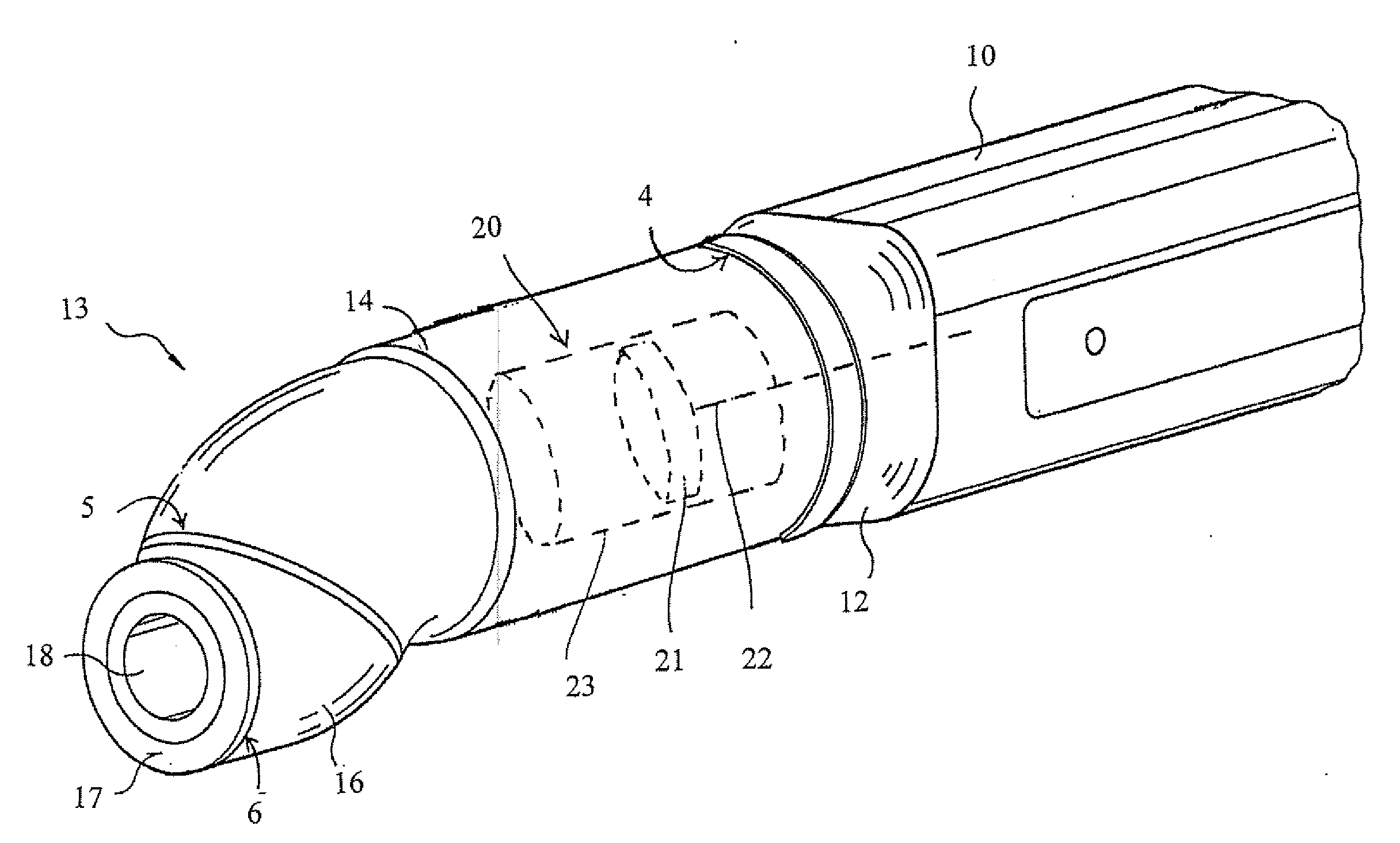
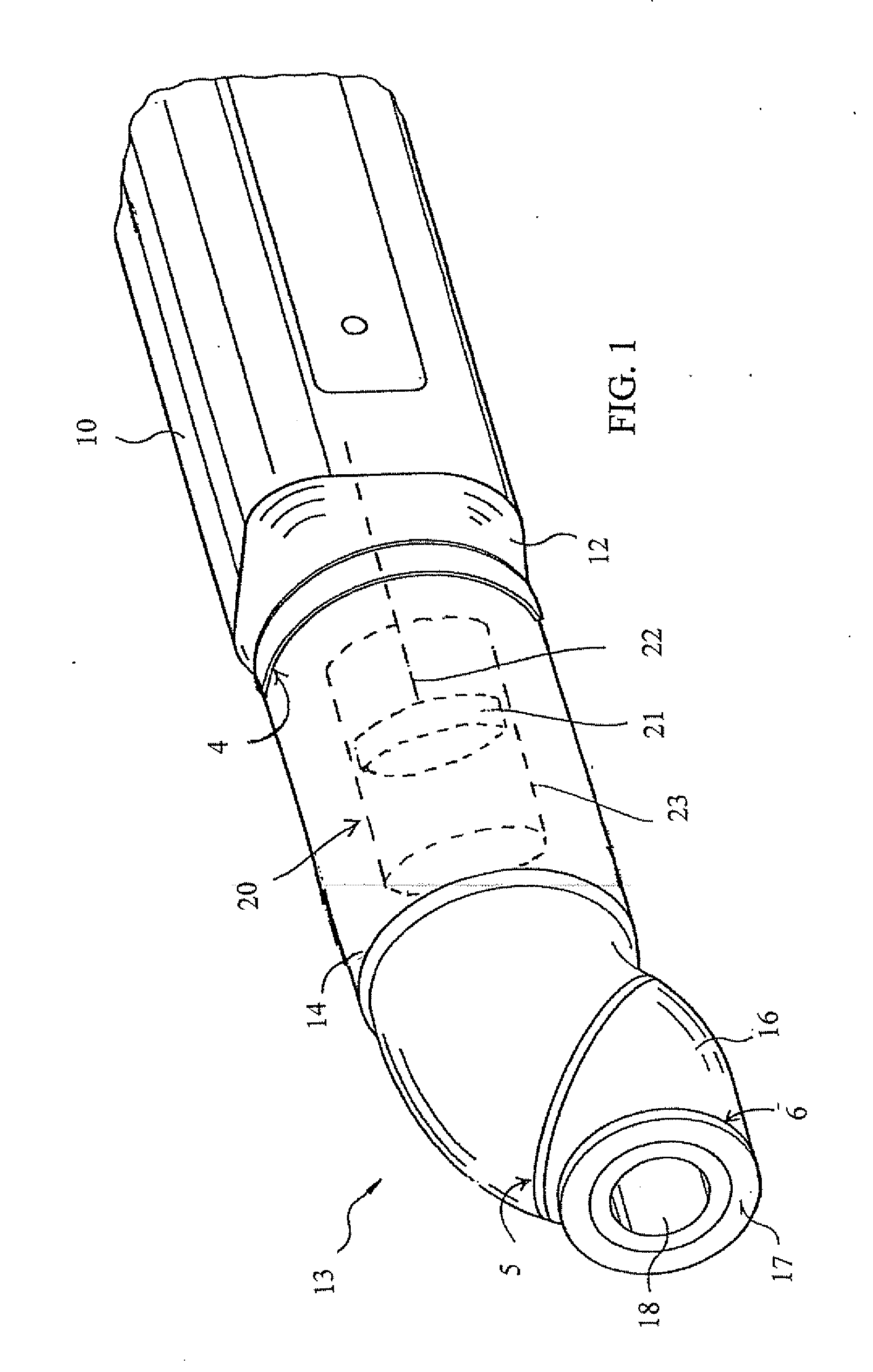
[0025]The front part of the arm 10 of a painting robot depicted in FIG. 1 has a flange 12 at its end, on which is fastened the triaxial hand joint 13, also often termed the hand axis. The hand joint 13 consists of the first axial member 14, mounted so that it can rotate on the flange 12 of the arm 10, and the second axial member 16, able to rotate relative to the axial member 14. The hand joint or at least its axial members are generally configured as basically inseparable units. The three degrees of freedom of the hand joint 13 are denoted as axes 4, 5 and 6, as is usual with robots. On the flange 17 of the second axial member 16, and able to rotate relative to it, is mounted the atomizer (not depicted) of the painting robot on the hand joint 13, which is usually detachable and in many instances it can be automatically replaced by another atomizer. Depicted 18 is the conduit opening for the usual cables, hoses and other lines running through the hand joint on the inside, to and fro...


PUM


Abstract

The piston dispenser for the measured supplying of material to the atomizer of a painting robot is arranged in the hand joint of the robot. Various feasible embodiments of the dispensing cylinder of this piston dispenser are described.

Description

CROSS-REFERENCE TO RELATED APPLICATIONS[0001]This application claims the benefit of U.S. Provisional Patent Application Ser. No. 60 / 729,443 filed on Oct. 21, 2005, and also claims the benefit of U.S. Provisional Patent Application Ser. No. 60 / 729,442 filed Oct. 21, 2005 which is incorporated by reference herein in its entirety.FIELD OF THE INVENTION[0002]The invention concerns an automatically controlled coating machine for the mass production coating of work pieces and, in particular, a painting robot for the painting of work pieces such as automotive bodies with an electrostatic or other type of atomizer.BACKGROUND[0003]During the electrostatic coating with direct charging of an electrically conductive coating material of varying color, it is known to employ an intermediate reservoir for the necessary potential separation between the grounded color changer, which consists of a valve arrangement, and the atomizer, which is placed under high voltage. The reservoir can be filled by t...

Claims


Application Information

Patent Timeline
IPC IPC(8): B05C1/00
CPCB05B5/1633B05B5/1675B05B12/14B05B12/1454B05B13/0431
Inventor HERRE, FRANKHAAS, JURGENVETTERS, HANSBAUMANN, MICHAELHEZEL, THOMASMAXHARRAJ, BEKIMMAXHARRAJ, NEDIMEGRIGOLEIT, JANFREY, MARCUSMARTIN, HERBERT
Owner DURR SYST INC
Why Eureka
Try Eureka