Showerhead for chemical vapor deposition (CVD) apparatus

Inactive Publication Date: 2008-10-02
STRUCTURED MATERIALS
View PDF8 Cites 57 Cited by
  • Summary
  • Abstract
  • Description
  • Claims
  • Application Information

AI Technical Summary

Benefits of technology

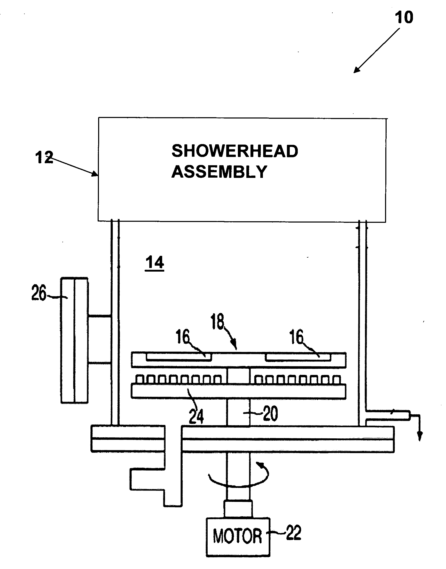
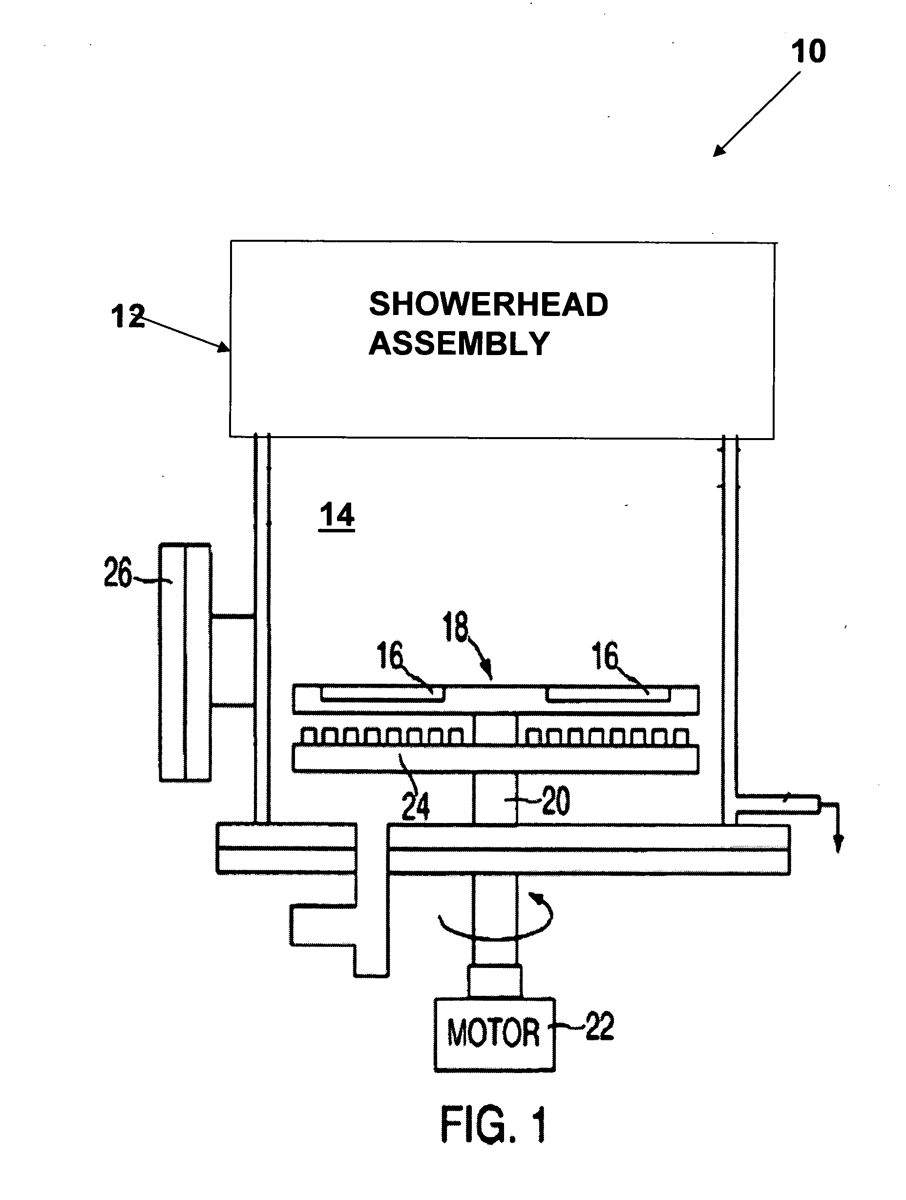
[0002]This application is directed to a showerhead assembly within the preferred embodiment of Chemical Vapor Deposition (CVD) apparatus and

Problems solved by technology

Reactions at the precursor inlet mechanism, commonly called a showerhead, are generally detrimental to the process because such coatings formed by the reactions can disturb or otherwise block desired flow patterns and or su

Method used


Image

  • Showerhead for chemical vapor deposition (CVD) apparatus
  • Showerhead for chemical vapor deposition (CVD) apparatus
  • Showerhead for chemical vapor deposition (CVD) apparatus

Examples


second embodiment

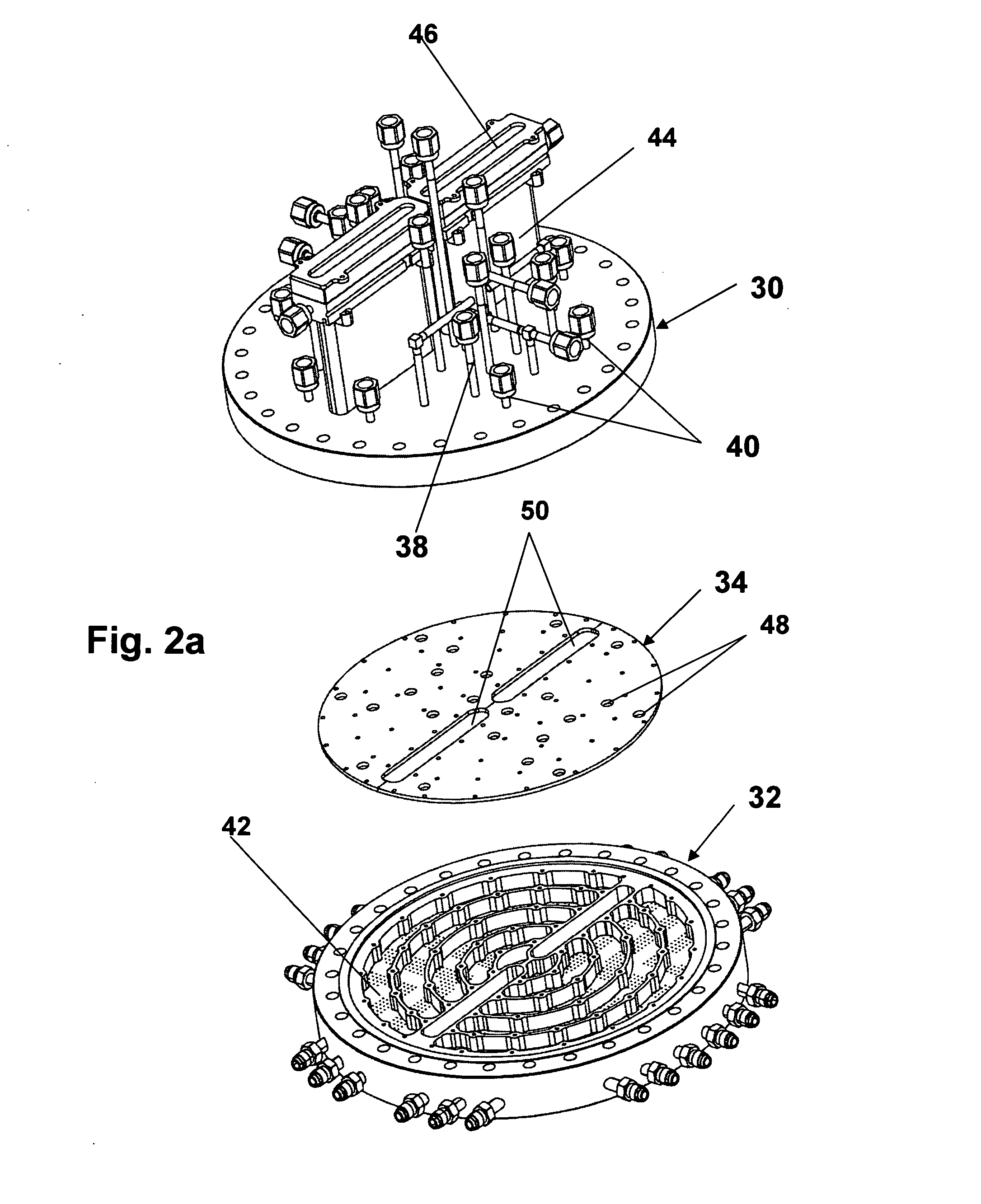
[0029]FIG. 4 is an exploded view, looking downwardly, of a showerhead assembly 86 in accordance with the present invention. In this embodiment one of the viewports in upper showerhead flange 30 has been replaced with an opening 88 to permit the insertion of one or more plasma generating electrodes to generate ionic, excited and or elemental gas phase species of the reactant vapors. As shown in the drawing a first electrode 90 has a shorter shaft which may be used to generate a plasma in plenum 36 in upper showerhead flange 30. A second electrode 92 has a relatively longer shaft which may be used to generate a plasma in plenum 42 in lower showerhead flange 32. Upper showerhead flange 30 may preferably include fluid channels so as to dissipate the heat caused by the generated plasma. It should be noted that upper showerhead flange 30 could include two openings 88 to permit both electrodes 90 and 92 to be used simultaneously and that an electrode can be used in conjunction with two vie...

third embodiment

[0030]FIG. 5a is an exploded view, looking downwardly, of lower flange 32 of the showerhead assembly in accordance with the present invention; and FIG. 5b is a sectional view cut along a vertical plane of lower flange 32. This embodiment includes a series of semicircular, U-shaped in cross-section, troughs 96 which are configured to be positioned within injections zones 62 formed in plenum 42 in lower flange 32. Troughs 96 are used to hold a material within the showerhead and within the gas flow and at a temperature that creates vapors at a specific vapor pressure and when flow is passed over it is used to carry the vapors into the reactor. A port, not shown, in the showerhead can be used to refill the materials. Most advantageous is a material which melts so it can more easily fill troughs 96 uniformly.

[0031]Also included in this embodiment is a cover plate 98 disposed on the underside of lower flange 32. Cover plate 98 is used to form a third and lowest level plenum. Cover plate 9...


PUM

PropertyMeasurementUnit
Temperatureaaaaaaaaaa
Permeabilityaaaaaaaaaa
Distributionaaaaaaaaaa

Abstract

A reactant vapor distribution assembly for Chemical Vapor Deposition (CVD) apparatus which includes an upper flange which has a plenum disposed on its lower face and vapor injectors for injecting reactant vapors into the plenum. The distribution assembly also includes a lower flange having a peripheral rim surrounding a lower wall and a plenum on its upper face, certain of the vapor injectors are used to inject reactant vapors into this plenum. The lower flange includes fluid channels bored in the lower wall beneath the plenum and a number of gas flow openings bored in the lower wall of the lower flange to permit the precursor gases to flow from the plenum into the deposition chamber. The fluid channels may be used to heat or cool the flange. The lower flange has no welds or joints facing the hostile environment of the deposition chamber and all critical parts of the lower flange may be formed from a single billet of material.

Description

REFERENCE TO RELATED APPLICATIONS[0001]This application claims priority from U.S. provisional application Ser. No. 60 / 920,125 filed Mar. 27, 2007.BACKGROUND AND SUMMARY OF THE INVENTION[0002]This application is directed to a showerhead assembly within the preferred embodiment of Chemical Vapor Deposition (CVD) apparatus and more specifically to an improved showerhead design allowing cooling and uniform distribution of the reactant gases in a deposition reactor.[0003]Chemical Vapor Deposition (CVD) systems are widely used to deposit elemental, alloy and compound films in the manufacture of electronic devices, such as integrated circuits formed by the sequential or simultaneous deposition of compounds upon a heated substrate, which is usually in the form of a wafer that is typically mounted on a “susceptor” which may or may not rotate. A showerhead provides distribution and passage for one or more reactant gases with the deposition chamber. The reactants are transported to the surface...

Claims


Application Information

Patent Timeline
IPC IPC(8): C23C16/00
CPCC23C16/45565C23C16/4557C23C16/45572
Inventor TOMPA, GARY S.
Owner STRUCTURED MATERIALS
Why Eureka
Try Eureka