

Method and Device for Control of a Reversible Belt Tensioner
- Summary
- Abstract
- Description
- Claims
- Application Information
AI Technical Summary
Benefits of technology
Problems solved by technology
Method used
Image

Examples
Embodiment Construction
[0026]Parts which correspond to one another are provided with the same reference symbols in all the figures.
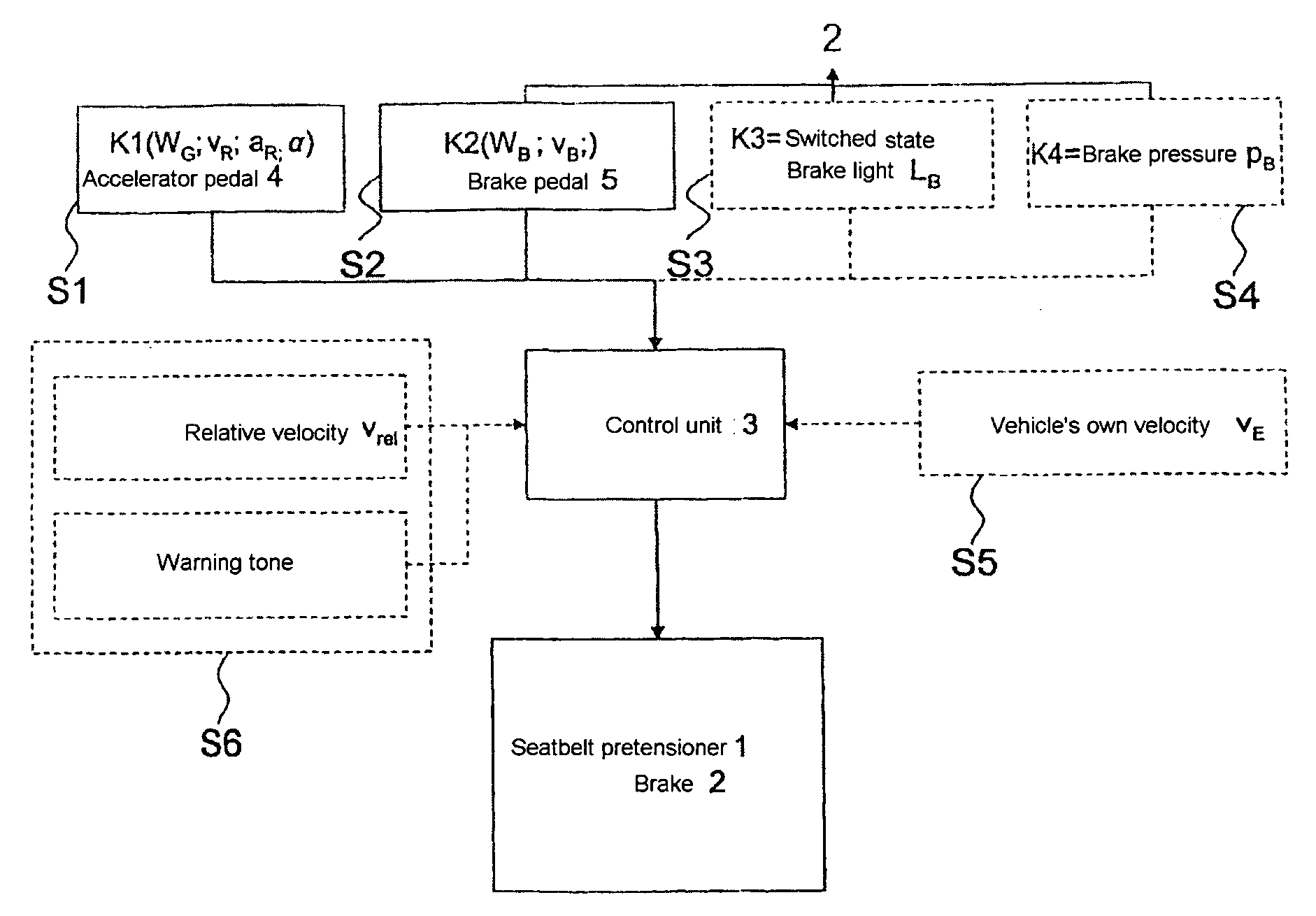
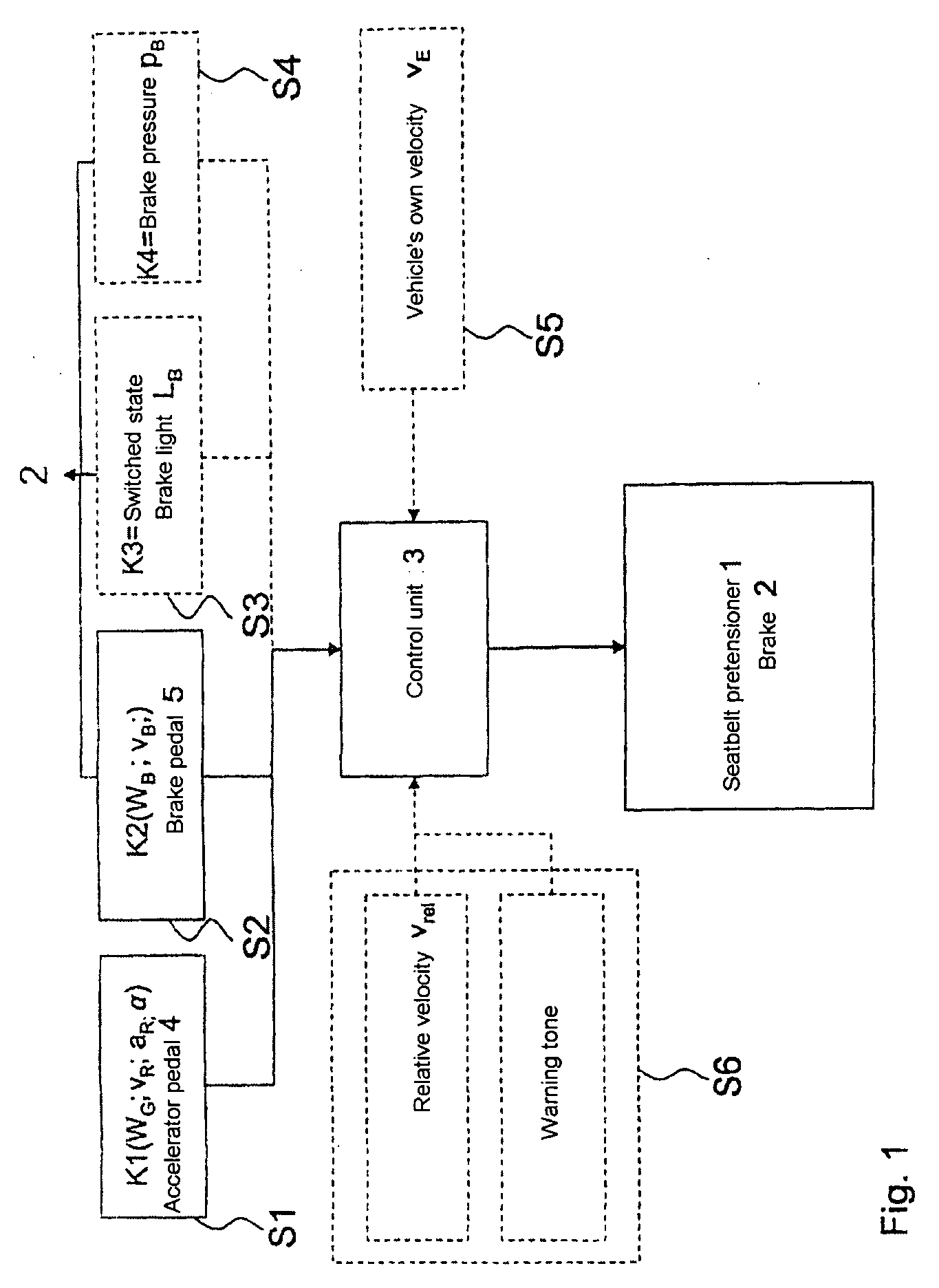
[0027]FIG. 1 is a block illustration of a reversible seatbelt pretensioner 1 of a vehicle (not illustrated in more detail) which has a brake 2. The seatbelt pretensioner 1 and brake 2 are controlled by means of a control unit 3. Depending on the type and design, the brake 2 and the seatbelt pretensioner 1 can each have an associated control unit 3.
[0028]For rapid and early, in particular predictive activation of the seatbelt pretensioner 1 in the event of a critical situation, for example a possible accident situation or hazardous situation, the control unit 3 is connected to a number of sensors S1 to Sn which acquire characteristic variables K1 to Kn of the accelerator pedal 4 and of the brake 2 of the vehicle.
[0029]For example the position WG of the accelerator pedal, the release speed vR and / or the release acceleration aR of the accelerator pedal 4 are acquired as a charact...
PUM
 Abstract
Description
Claims
Application Information