Method and Apparatus for Light Emission Utilizing an OLED with a Microcavity

a technology of light emission and microcavity, which is applied in the manufacture of electrode systems, electric discharge tubes/lamps, discharge tubes luminescnet screens, etc., can solve the problems of about 80% of the light generated by the device being trapped and about 20% of the light being able to get out, and achieves enhanced light coupling efficiency and broad color spectrum

Inactive Publication Date: 2008-10-02
UNIV OF FLORIDA RES FOUNDATION INC
View PDF39 Cites 15 Cited by
  • Summary
  • Abstract
  • Description
  • Claims
  • Application Information

AI Technical Summary

Benefits of technology

[0004]Embodiments of the present invention pertain to an organic light emitting diode (OLED) device and method for producing light of one or more desired wavelengths. An embodiment relates to a method for manufacturing an OLED for producing light of one or more desired wavelengths. An embodiment of an OLED device is capable of providing an enhanced light coupling efficiency. An additional embodiment of an OLED device is capable of providing a broad color spectrum.

Problems solved by technology

One of the issues with OLEDs is that about 80% of the light generated by the device is trapped within the glass substrate 1 and only about 20% of the light can get out.

Method used


Image

  • Method and Apparatus for Light Emission Utilizing an OLED with a Microcavity
  • Method and Apparatus for Light Emission Utilizing an OLED with a Microcavity
  • Method and Apparatus for Light Emission Utilizing an OLED with a Microcavity

Examples


Embodiment Construction

[0017]Embodiments of the present invention pertain to an organic light emitting diode (OLED) device and method for producing light of one or more desired wavelengths. An embodiment relates to a method for manufacturing an OLED for producing light of one or more desired wavelengths. An embodiment of an OLED device is capable of providing an enhanced light coupling efficiency. An additional embodiment of an OLED device is capable of providing a broad color spectrum.

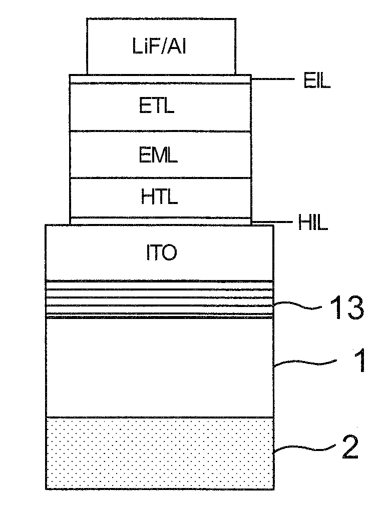
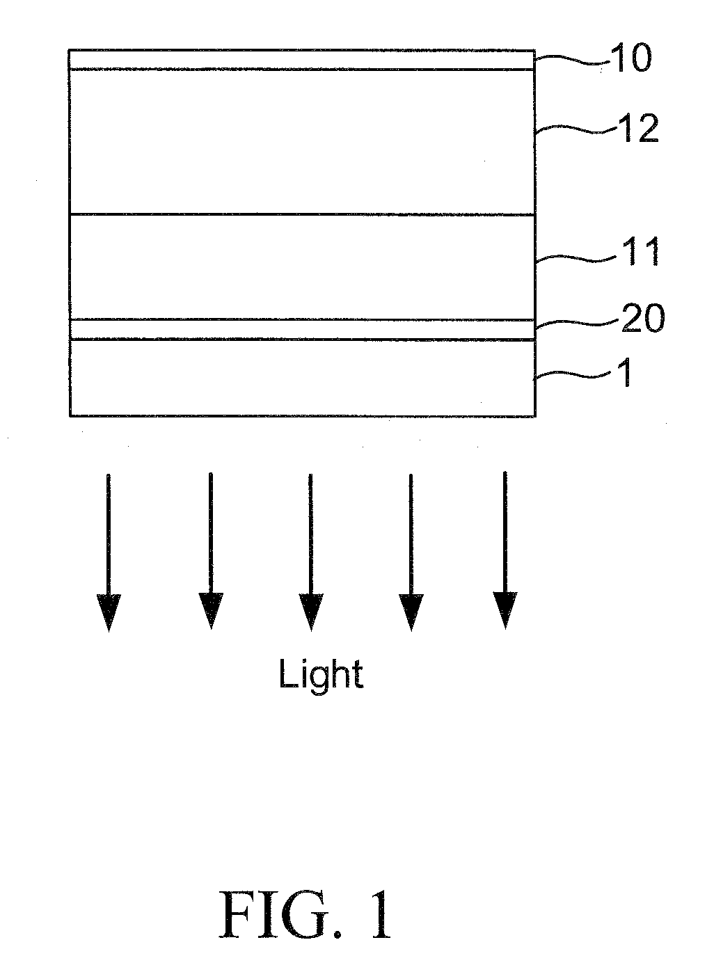
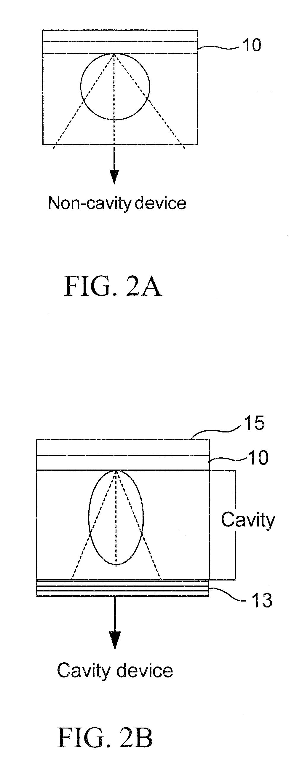
[0018]Embodiments of the subject invention can include a blue light emitting organic LED (OLED) structure incorporating a microcavity structure to partially reflect the light generated in the OLED structure back into the OLED structure, so as to create a cavity effect within the device to enhance the output from the OLED. In an embodiment, the microcavity can be created with a reflective material on one end of the OLED and a reflective material at the other end of the OLED. FIG. 2B shows an electrode 10 and a reflective lay...


PUM


Abstract

Provided is an OLED device and method of making the OLED device. According to an embodiment, the OLED device incorporates a microcavity structure including a dielectric mirror formed on a glass substrate, an anode formed above the dielectric mirror, an organic film layer formed above the anode, and a reflective electrode formed above the organic film layer such that the cavity is formed in the organic film layer by the dielectric mirror and the reflective electrode. The OLED device with microcavity structure can incorporate one or more phosphors deposited on an underside of the glass substrate such that light of additional wavelengths can be generated by the OLED device.

Description

CROSS-REFERENCE TO RELATED APPLICATIONS[0001]This application is a continuation-in-part of International Patent Application No. PCT / US2006 / 040748, filed Oct. 16, 2006, which claims the benefit of U.S. Provisional Patent Application Ser. No. 60 / 726,865, filed Oct. 14, 2005, the disclosures of which are hereby incorporated by reference herein in their entirety.BACKGROUND OF INVENTION[0002]Organic light emitting diodes (OLEDs) have the potential of being used in solid state lighting to replace conventional light sources such as incandescent light sources. The traditional light sources have efficiencies lower than 15 lm / W, where OLED have the potential of reaching 100 lm / W. Potential uses for OLEDs include lighting products, backlights for LCD panels, and flat panel displays.[0003]A typical OLED device structure is shown in FIG. 1. The device has multilayer organic films sandwiched between a metal cathode 10 and an indium tin oxide transparent electrode 20. Typically, a hole transportin...

Claims


Application Information

Patent Timeline
Patent Type & Authority Applications(United States)
IPC IPC(8): H01L51/50H01J9/02
CPCH01L51/5265H01L51/5036H10K50/125H10K50/852
Inventor SO, FRANKY
Owner UNIV OF FLORIDA RES FOUNDATION INC
Why Eureka
Try Eureka