Reduced-Delay Clocked Logic

Inactive Publication Date: 2008-10-02
POLARIS INNOVATIONS
View PDF4 Cites 7 Cited by
  • Summary
  • Abstract
  • Description
  • Claims
  • Application Information

AI Technical Summary

Benefits of technology

[0003]According to the methods and apparatus taught herein, delay in a clocked logic circuit is reduced by partially determining a next state of the clocked logic circuit based on a current state of the clocked logic circuit during a first portion of a clock cycle. The partially determined next state of the clocked logic circuit is prevented

Problems solved by technology

Otherwise, circuit behavior becomes unpredictable and may result in failure.
Performance of clocked logic circuitry is limited by the amount of time needed to process previous sta

Method used


Image

  • Reduced-Delay Clocked Logic
  • Reduced-Delay Clocked Logic
  • Reduced-Delay Clocked Logic

Examples


Embodiment Construction

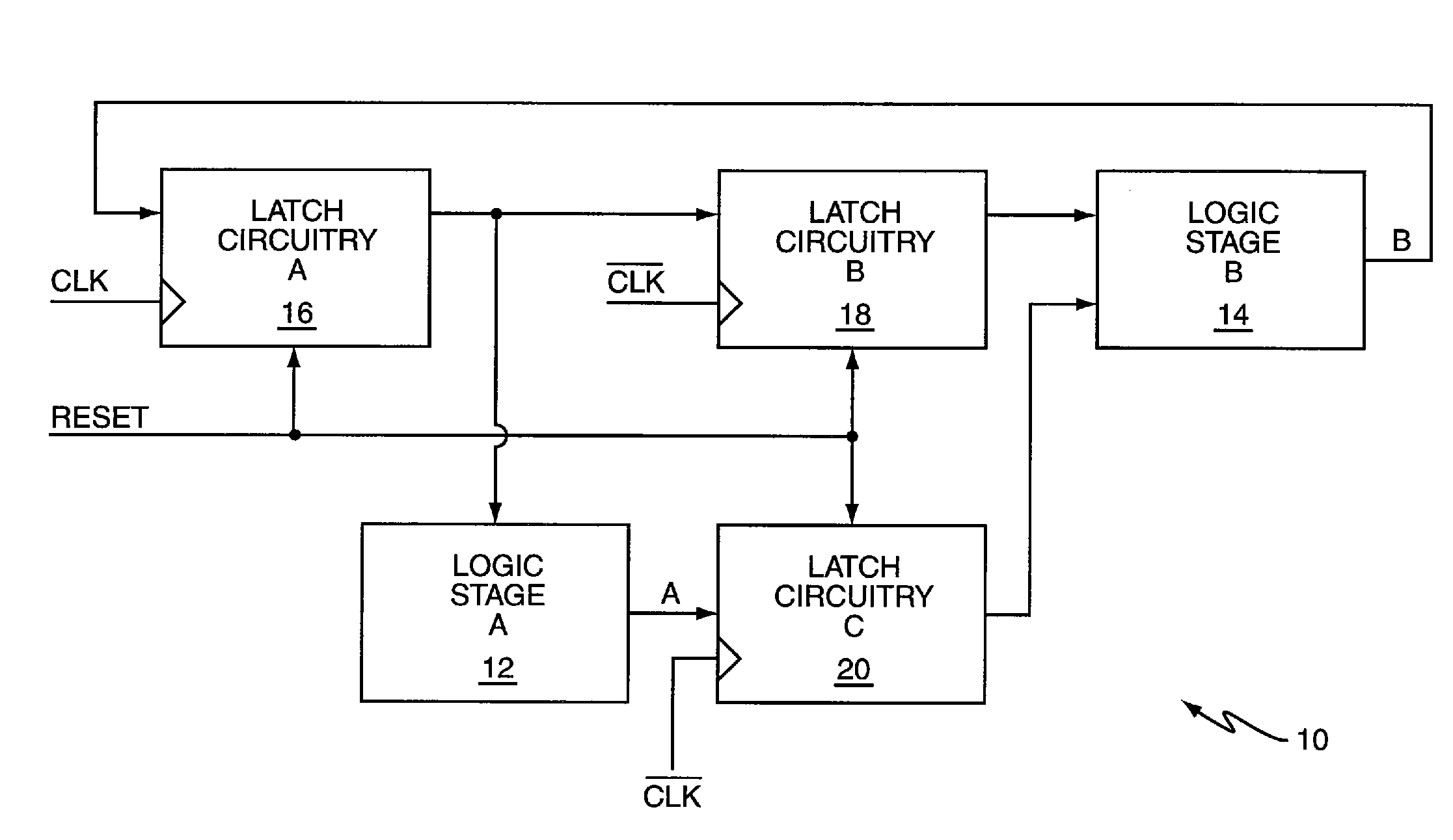
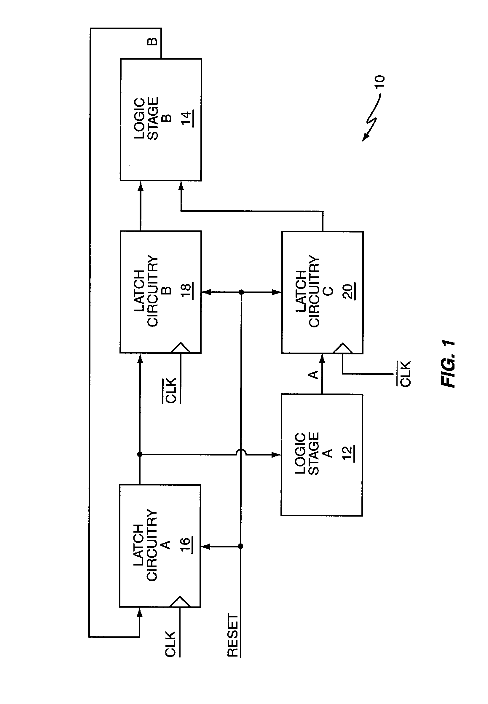
[0011]FIG. 1 illustrates an embodiment of a clocked logic circuit 10 such as a sequential circuit, state machine, data path, counter, arithmetic logic unit, processor, or the like. The clocked logic circuit 10 implements one or more functions and is segmented into at least two stages 12, 14. The circuit 10 advances from state-to-state responsive to transitions in a clock signal (CLK). A first logic stage 12 partially determines a next state of the circuit 10 based on current state information provided to the first stage 12 during a first portion of a clock cycle, e.g., when the clock signal is at a logic high level. The information processed by the first stage 12 may be the current state of the clocked logic circuit 10 (as shown in FIG. 1), the current state of other logic circuits (not shown) or both. Regardless, a second logic stage 14 completes determination of the next logic state based on the first stage results during a subsequent portion of the clock cycle, e.g., when the clo...


PUM


Abstract

Delay in a clocked logic circuit is reduced by partially determining a next state of the clocked logic circuit based on a current state of the clocked logic circuit during a first portion of a clock cycle. The partially determined next state of the clocked logic circuit is prevented from affecting the current state of the clocked logic circuit during the first portion of the clock cycle. The next state of the clocked logic circuit is completely determined based on a previous state of the clocked logic circuit and the partially determined next state of the clocked logic circuit during a second portion of the clock cycle.

Description

BACKGROUND OF THE INVENTION[0001]Clocked logic circuitry such as sequential circuits, state machines, data paths, counters, arithmetic logic units, processors, or the like use a clock signal to advance the circuitry from state to state. The current state of a clocked logic circuit is a function of its previous state, the previous state of other circuitry, or both. Circuit state may be advanced responsive to the rising edge of a clock signal, falling edge, or both. The input to clocked logic circuitry does not affect the present logic state when the clock signal is inactive (i.e., not rising and / or falling). Circuit operation should be completed within a fixed interval of time between two clock pulses, called a ‘clock cycle’, to ensure reliable operation of clocked logic circuitry. Otherwise, circuit behavior becomes unpredictable and may result in failure.[0002]Performance of clocked logic circuitry is limited by the amount of time needed to process previous state information to pro...

Claims


Application Information

Patent Timeline
IPC IPC(8): H03K19/00
CPCH03K3/03
Inventor TAMLYN, ROBERT
Owner POLARIS INNOVATIONS
Why Eureka
Try Eureka