
Nozzle plate, ink ejection head, and image forming apparatus

Inactive Publication Date: 2008-10-02
FUJIFILM CORP
View PDF1 Cites 7 Cited by
  • Summary
  • Abstract
  • Description
  • Claims
  • Application Information

AI Technical Summary

Benefits of technology

[0008]The present invention has been contrived in view of these circumstances, an object thereof being to provide a nozzle plate which prevents peeling away of the liquid repelling layer formed on the ejection surface of the nozzle plate, as well as maintaining shape and dimensional accuracy, by providing ink resistant properties in the perimeter of the ejection ports of the nozzles of the nozzle plate.
[0010]According to this aspect of the present invention, since the p-type doped layer is formed at least about the whole circumference of the edge section that defines the inner perimeter of the ejection port of the nozzle, then the alkali resistance of the edge section of the nozzle is improved by the p-type doped layer, and it is possible to maintain the dimensional accuracy of the edge section of the nozzle. Moreover, since the wear resistance is improved by the presence of the p-type doped layer, the durability of the ejection port of the nozzle with respect to wiping is improved, and it is possible to maintain the dimensional accuracy of the edge section of the nozzle. Furthermore, by forming the p-type doped layer on the inner surface of the nozzle as well, the alkali resistance of the inner surface of the nozzle is improved, and the dimensional accuracy of the inner surface of the nozzle can be maintained.
[0012]According to this aspect of the present invention, since the p-type doped layer is formed on the inner surface of the nozzle, the alkali resistance of the inner surface of the nozzle is improved, and the dimensional accuracy of the inner surface of the nozzle can be maintained. Moreover, the ink wetting properties of the inner surface of the nozzle are improved by the p-type doped layer, and incorporation of air bubbles to the ink through the ink ejection port of the nozzle is not liable to occur. Furthermore, since the p-type doped layer is formed over the range from the edge section of the ink ejection port to the position of the boundary region between the oxide layer and the liquid repelling layer on the inner surface of the nozzle, then the boundary region of the oxide layer and the liquid repelling layer is covered with the p-type doped layer and does not face directly onto the nozzle, and hence the ink does not permeate into the boundary region of the oxide layer and the liquid repelling layer and there is no risk of the liquid repelling layer peeling away from the oxide layer.
[0014]According to this aspect of the present invention, by more reliably providing ink resistance properties in the perimeter of the ejection port of the nozzle, maintenance of the shape and dimensional accuracy can be achieved. Furthermore, it is possible to prevent peeling away of the liquid repelling layer, in a more reliable fashion.
[0017]According to the present invention, by providing ink resistance properties in the perimeter of the ejection port of the nozzle in the nozzle plate, the shape and dimensional accuracy can be maintained, and it is possible to prevent the liquid repelling layer formed on the ejection surface of the nozzle plate from peeling away.

Problems solved by technology

Then, edge portions that define ejection ports of nozzles in the nozzle plate do not have ink resistant properties, and it is not possible to maintain the dimensional accuracy of the ejection ports of the nozzles.
In this case, since the bonding region between the oxide layer and the liquid repelling layer is exposed on the inner surface of the nozzle, then ink permeates through the bonding region, and there is a risk that the liquid repelling layer may peel away from the oxide layer formed on the silicon substrate.

Method used


Image

  • Nozzle plate, ink ejection head, and image forming apparatus
  • Nozzle plate, ink ejection head, and image forming apparatus
  • Nozzle plate, ink ejection head, and image forming apparatus

Examples


Embodiment Construction

Description of Nozzle Plate

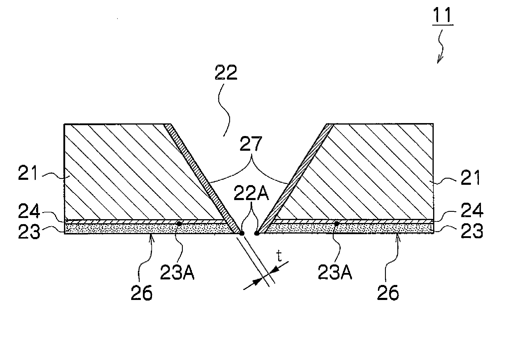
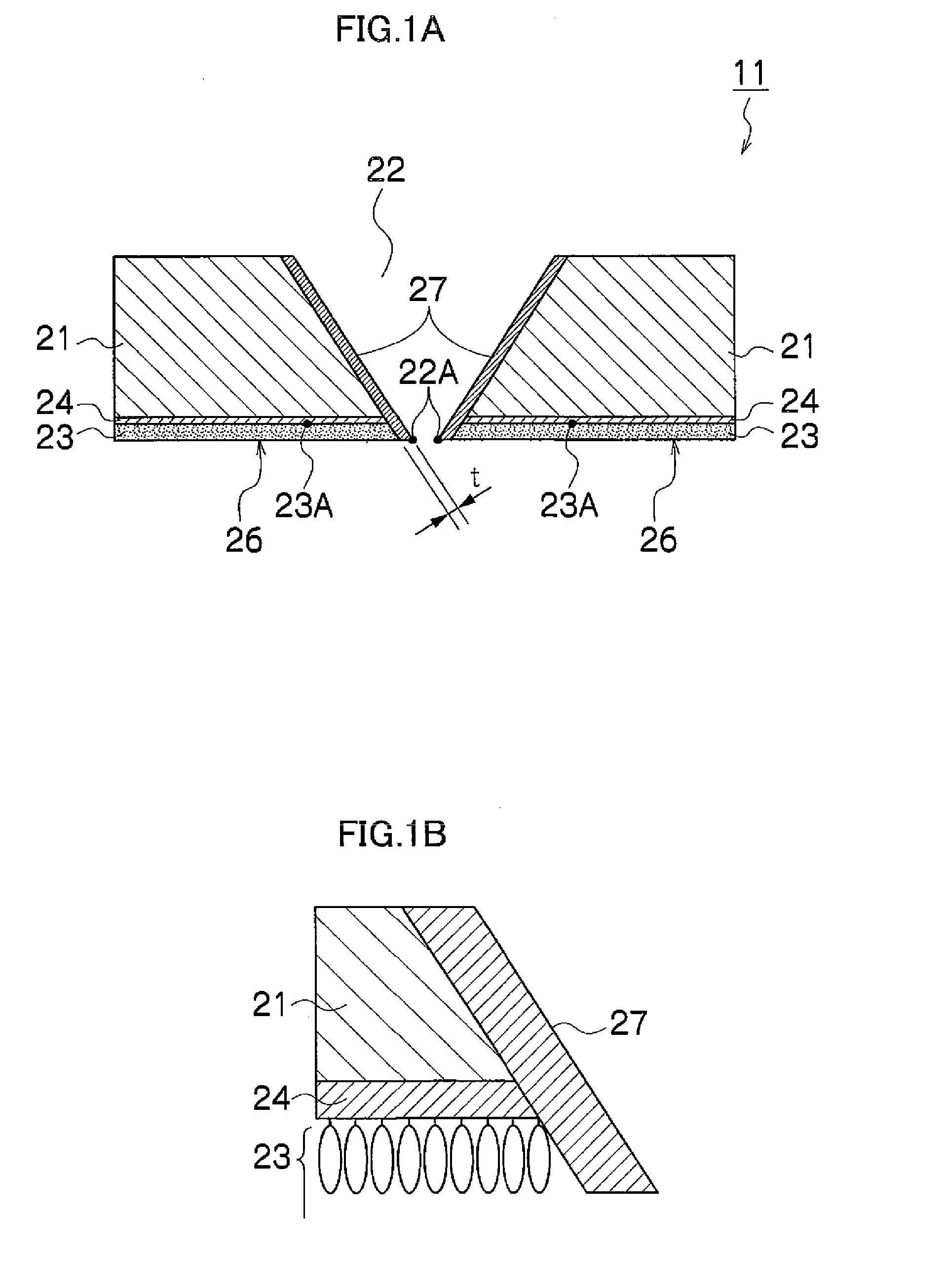
[0030]FIG. 1A is a cross-sectional diagram of a nozzle plate 11 according to an embodiment of the present invention, in the ink ejection direction in the vicinity of a nozzle 22. FIG. 1B is an enlarged diagram of the bonding region between a liquid repelling layer 23 and an oxide layer 24.

[0031]As shown in FIG. 1A, the nozzle plate 11 includes a plate substrate 21, the nozzle 22, the liquid repelling layer 23, the oxide layer 24, and a p-type doped layer 27. The plate substrate 21 is a plate-shaped silicon substrate. The nozzle 22 is formed in such a manner that the internal diameter thereof narrows toward the ink ejection direction, and thus the nozzle 22 tapers in the ink ejection direction. The nozzle 22 has an edge portion 22A of the inner perimeter of the ink ejection port at the endmost portion of the tapering shape.

[0032]It is one of the characteristic features of the present embodiment that the p-type doped layer 27 is formed about the whole perime...


PUM


Abstract

A nozzle plate includes: a plate substrate in which a nozzle is formed, ink being ejected through an ejection port of the nozzle in the plate substrate; and a p-type doped layer which forms a whole perimeter of an edge portion defining an inner perimeter of the ejection port of the nozzle in the plate substrate.

Description

BACKGROUND OF THE INVENTION[0001]1. Field of the Invention[0002]The present invention relates to a nozzle plate, an ink ejection head and an image forming apparatus, and more particularly, to a nozzle plate arranged in a recording head in an inkjet printer.[0003]2. Description of the Related Art[0004]In general, the inkjet printer uses alkaline ink, and the inkjet printer has an inkjet head constituted of a silicon substrate, which has a low resistance to alkali.[0005]Japanese Patent Application Publication No. 2001-328263 discloses an inkjet head in which inner faces of a pressure chamber are formed in a silicon substrate and a face of a diaphragm facing the pressure chamber is also formed in the silicon substrate. Since the faces of the pressure chamber and the diaphragm make contact with the ink, then they are made resistant to alkali by being formed with a p-type doped layer on them.[0006]However, in Japanese Patent Application Publication No. 2001-328263, the p-type doped layer...

Claims


Application Information

Patent Timeline
IPC IPC(8): B41J2/14B41J2/16
CPCB41J2/1433B41J2/1606B41J2/162B41J2/1628B41J2/1629B41J2/1631
Inventor OHTA, HIROSHI
Owner FUJIFILM CORP
Learn More