Imaging apparatus

Active Publication Date: 2008-10-02
FUJIFILM CORP
View PDF8 Cites 69 Cited by
  • Summary
  • Abstract
  • Description
  • Claims
  • Application Information

AI Technical Summary

Benefits of technology

[0018]According to the present invention, the imaging apparatus is provided with the distortion corrector that performs the image conversion processing to correct the optical and the wide-angle distortion. Therefore, an image with little distortion can easily be produced.

Problems solved by technology

Meanwhile, when a subject image is formed on a photographic film or an image sensor through a lens, the image is sometimes blurred or distorted.
A main cause of such blur and distortion is aberration of the lens used.
The distortion of image, on the other hand, is caused by distortion aberration.
Therefore, in a zoom lens whose aperture stop changes the relative position to the lens system, it is difficult to reduce the optical distortion uniformly.
Apart from the optical distortion, there is also known wide-angle distortion.
Since it results from a basic principle of the imaging apparatus, the wide-angle distortion cannot be eliminated completely.
In recent years, however, the wide-angle lenses with a 70 degree or more angle of view become popular, and loss of ima

Method used


Image

  • Imaging apparatus
  • Imaging apparatus
  • Imaging apparatus

Examples


first embodiment

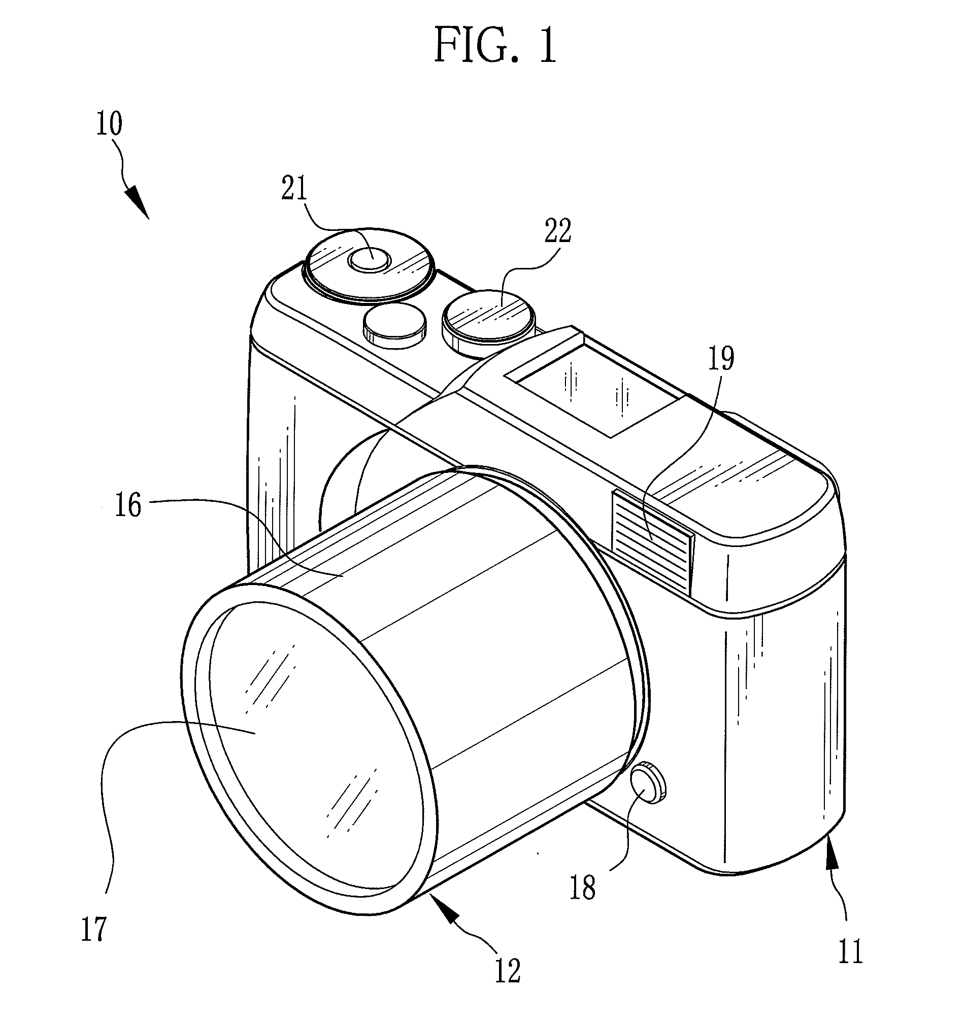
[0040]Referring to FIG. 1, a digital camera (imaging apparatus) 10 is composed of a camera body 11 and a detachable lens unit 12.

[0041]The lens unit 12 includes a lens barrel 16 and a taking lens 17 disposed in this lens barrel 16. The lens unit 12 and the camera body 11 have, on their mount portions, bayonet claws (not shown) to interlock with each other. When the lens unit 12 is mounted and rotated on the camera body 11, the bayonet claws interlock with each other, and the lens unit 12 is securely attached to the camera body 11. The lens unit 12 is detachable from the camera body 11 and changed with another lens unit having a different type of taking lens, if necessary.

[0042]On a front surface of the camera body 11 are provided an unlock button 18 and a flash emitter 19. To prevent accidental drop off of the lens barrel 16 from the camera body 11, the lens unit 12 is locked once the lens unit 12 is attached to the camera body 11. The unlock button 18 is pressed to unlock the lens ...

second embodiment

[0087]While in the above embodiment the coordinate transform processing to cause the negative distortion is applied to an image with the wide-angle distortion, the distortion aberration of a lens may be used to correct the wide-angle distortion. This is explained below as a second embodiment, in which the same components are designated by the same numerals as the first embodiment, and the detailed explanation thereof are omitted.

[0088]In FIG. 9, a taking lens 212 has such optical characteristic that produces the negative distortion in at least the wide-angle side. Nonetheless, it is more preferred that the taking lens 212 always produces the negative distortion across the wide-angle end to the telephoto end. In addition, a digital camera 210 can enables and disables (on / off) the wide-angle correction function. Therefore, as shown in FIG. 10, when an image is captured with the wide-angle distortion correction function being off, a distortion correction section 211 applies the coordin...

third embodiment

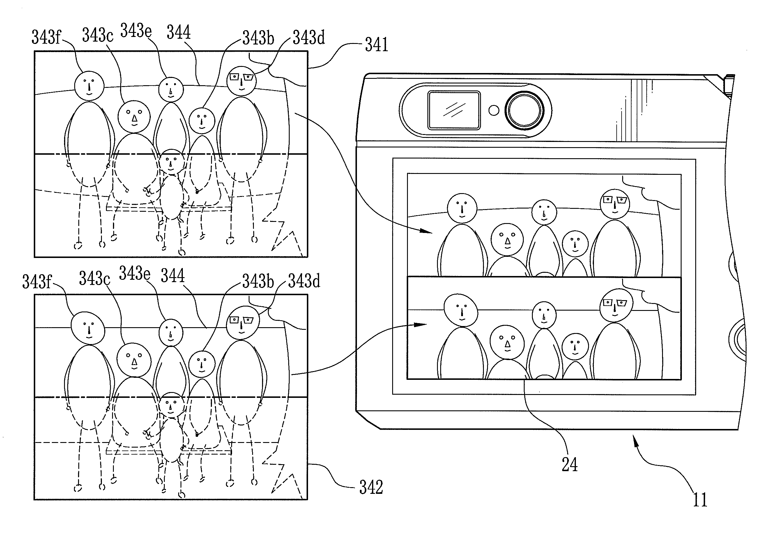
[0099]While in the first and second embodiments one of the wide-angle and the optical distortion is selectively corrected depending on the setting of the image capture modes, it may be possible to selectively correct one of the two depending on the type of a subject. This is explained below as a third embodiment, in which the same components are designated by the same numerals as the above embodiments, and the detailed explanation thereof is omitted.

[0100]As shown in FIG. 12, a digital camera 310 includes a face detecting section 311 to detect human faces in a picture frame. The obtained information, such as presence / absence of human faces, the position, size, number of the detected faces, is stored as face detection data to the SDRAM 42. The face detection data is retrieved by a distortion correction section 312, and used to decide which to correct the optical distortion or the wide-angle distortion. The face detection is performed by so-called a pattern matching method that compar...


PUM


Abstract

A digital camera includes a distortion correction section, which is composed of a focal length determining section, a distortion evaluation section and a correction amount calculating section. The focal length determining section evaluates a focal length at the time of image capture. Based on the focal length, the distortion evaluation section evaluates the magnitude of wide-angle distortion and optical distortion in a captured image. Based on this evaluation, the distortion correction section selects an appropriate coefficient from an optical distortion correction coefficient table or a wide-angle distortion correction coefficient table. Using the selected coefficient, the correction amount calculating section applies a coordinate transform processing to cause positive or negative distortion to the captured image, and corrects the wide-angle distortion or the optical distortion.

Description

FIELD OF THE INVENTION[0001]The present invention relates to an imaging apparatus capable of correcting distortion, especially wide-angle distortion of a subject image.BACKGROUND OF THE INVENTION[0002]Digital cameras that have been popular in recent years obtain an image in the form of digital data. Unlike the photographic images, the digital image data can be subjected to various image processing that allows so-called retouching to modify the image and correct color in a later time. It is also a common technique during image capture to detect human faces in a picture frame and control to have a proper face size and appropriate brightness (see, for example, Japanese Patent Laid-open Publication No. 2004-320284 corresponding to U.S. Patent Application Publication No. 2004 / 0207743).[0003]Meanwhile, when a subject image is formed on a photographic film or an image sensor through a lens, the image is sometimes blurred or distorted. A main cause of such blur and distortion is aberration ...

Claims


Application Information

Patent Timeline
IPC IPC(8): H04N5/217H04N5/232
CPCH04N5/217H04N5/23219H04N5/3572H04N23/81H04N23/611H04N25/61
Inventor CHO, MICHIO
Owner FUJIFILM CORP
Why Eureka
Try Eureka