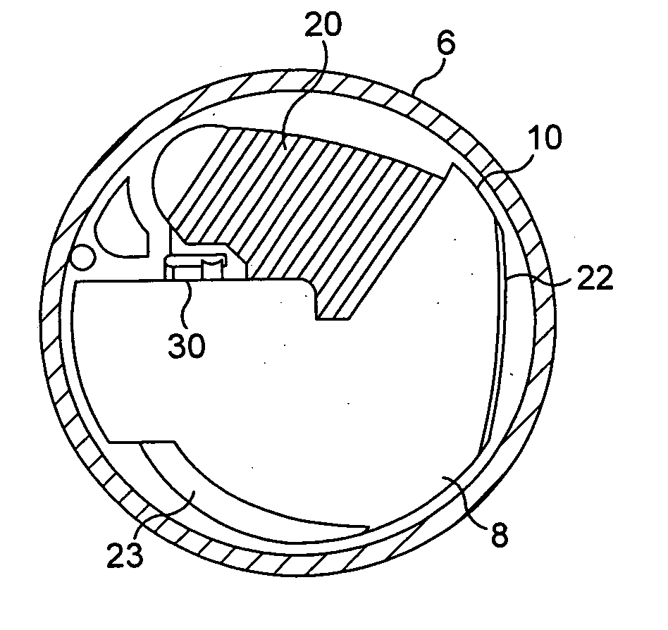
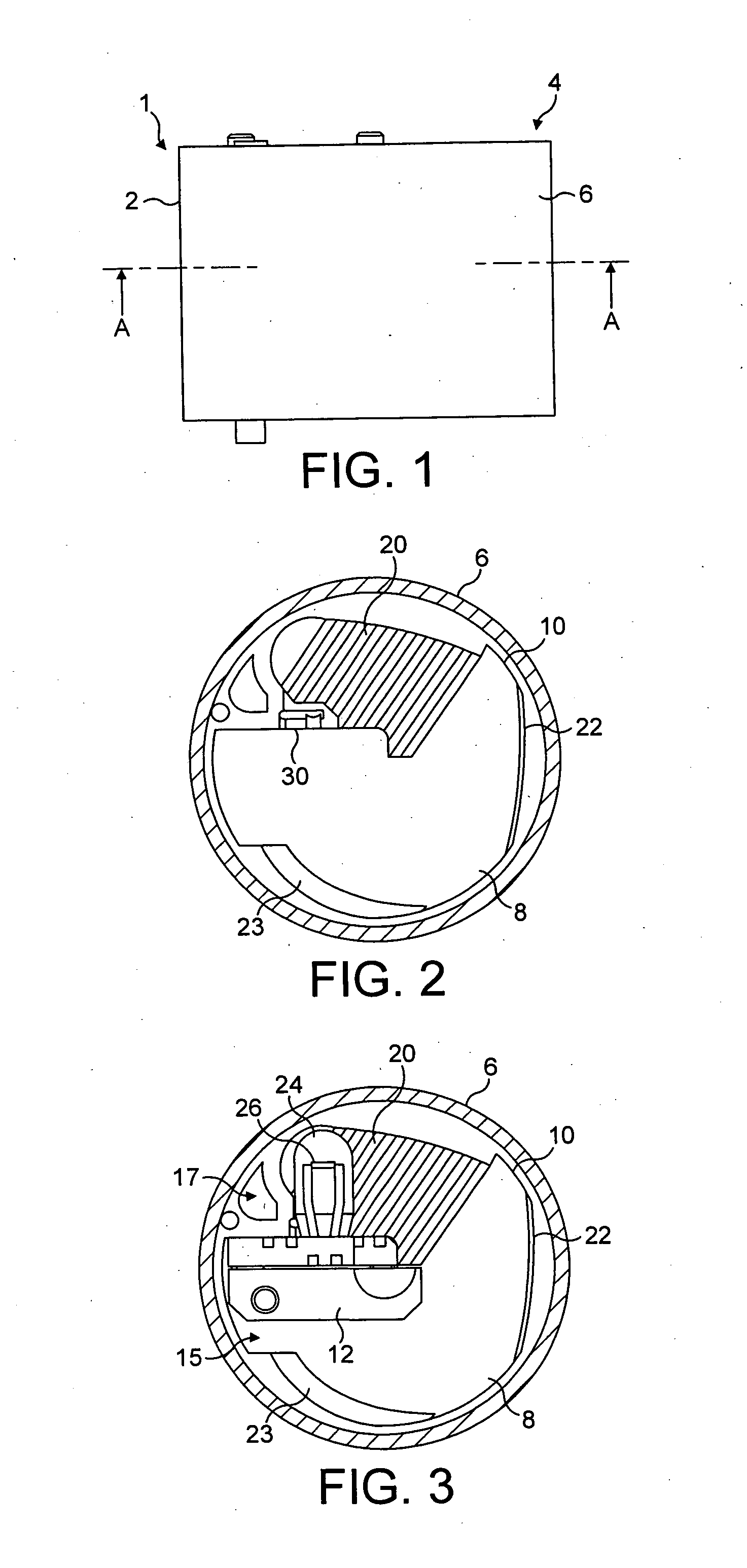
[0024]Preferably, the detector is in the form of a generally flat body (such as a disc) which extends obliquely from the inner wall of the body of the sensor into the chamber (i.e. not radially when the chamber is generally circular, nor directly towards the centre of the chamber where the chamber is not circular) such that the volume within the chamber on the first side of the detector is less than the volume within the chamber on the second side of the detector. In combination with the use of two or more reflectors which reduce the
divergence of the
light beam, and which are configured such that light falling on the detector is predominantly convergent, this allows a collector (see below) with a larger internal reflective surface area to be provided than would be the case if the planar detector extended inwards along a
radius of the chamber and bisected part of the chamber. This allows a larger collector to be provided which better controls the spatial and
angular distribution of light from the light-source which is directed onto the first reflector.
[0029]This has the effect that, to a first order of approximation, light which is emitted by the light source in the region of the centre of the part-spherical portion, will be reflected by the portion of the interior of a sphere and the reflected light will form a
mirror image of the light source. This reduces the sensitivity of the amount of light falling on the detector to the precise location of the light source. This increases tolerance to manufacturing imperfections, particularly those imperfections resulting in the light source not being coincident with the centre of the sphere portion, and also increases tolerance to movement of the light source in use. This is particularly relevant where the light source is the filament of an incandescent lamp which may move in use due to
thermal expansion, vibration, shocks etc. This is especially relevant in embodiments of the sensor in which the
optics are symmetric about a plane of symmetry, which is discussed further below. The use of a sphere portion is especially beneficial when the size of the light source is significant compared to the size of the collector, e.g. where the light source extends across more than 10% of the width of the collector in a plane which bifurcates the light source.
[0032]This allows the light source to be located further from the first reflector than would be the case if the light-emitting device extended into the collector towards the first reflector. This increases the
average path length from the light source to the detector.
[0035]The light-source may be elongate, for example, the light-source may be an elongate filament of an incandescent
bulb. The elongate light-source may be parallel to the length of the light-emitting device. The elongate light-source may be orthogonal to the length of the light-emitting device. The elongate light-source may be other than parallel to the axis of the collector. In embodiments with a plane of symmetry (discussed below) the elongate light-source may be other than symmetric about the plane of symmetry. This will occur if, as is common with the filament of incandescent bulbs, the filament is orthogonal to the length of the incandescent
bulb and the incandescent
bulb extends into the collector towards the rear of the collector. In this case, where the interior surface of the collector comprises part of the interior surface of a sphere, this has the effect of, to a first order of approximation, avoiding an
asymmetry in the distribution of light about the plane of symmetry.
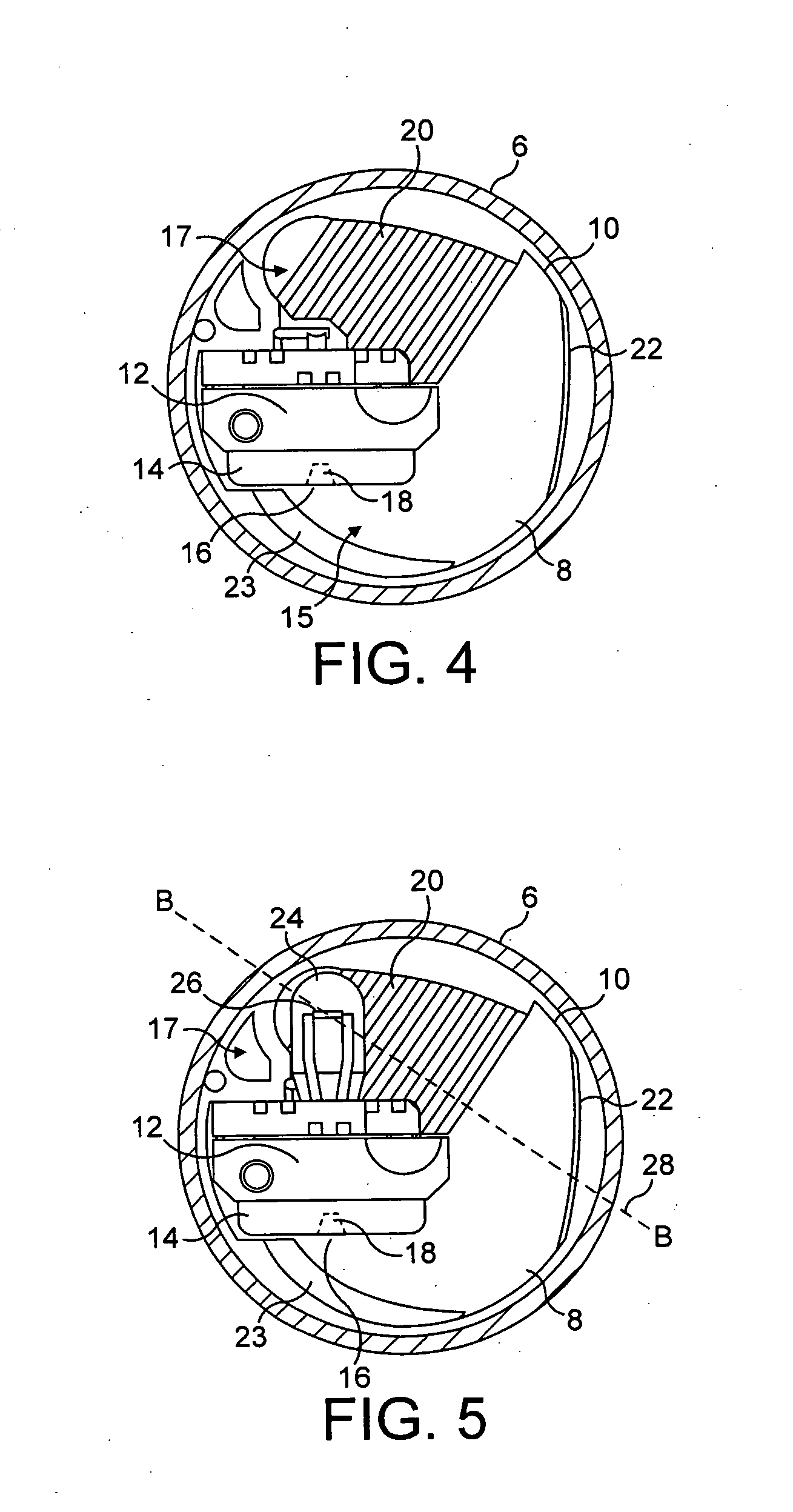
[0042]Preferably, the light source is centred on the plane of symmetry. Preferably, the light source is part of an elongate light-emitting device which extends into the collector in the plane of symmetry. Where the light-emitting device extends into the collector through an aperture in the reflective inner surface of the collector, this has the effect of distorting the pattern of reflection of light in comparison to an uninterrupted collector. However, where the measurement and reference detectors are located symmetrically on either side of the plane of symmetry and the light-emitting device extends into the collector in the plane of symmetry, the
distortion does not affect the relative amount of light which reaches the measurement and reference detectors, nor the
average path length of light which reaches the measurement and reference detectors. In this case, the light-emitting device will typically be symmetrical on either side of the plane of symmetry.
[0043]Either or both of the first and second reflectors are preferably concave in a plane which is orthogonal to the plane of symmetry and symmetric about the plane of symmetry. The collector and the first reflector are preferably configured such that the distribution of light reflected from the surface of the first reflector is bifurcated. Where the detector comprises separate measurement and reference detectors located symmetrically on either side of the plane of symmetry, the collector and reflectors are preferably configured such that the distribution of light which reaches the detector is bifurcated so that the intensity of light which falls on each of the measurement and reference detectors is greater than the intensity of light which is incident on the detector in the plane of symmetry between the measurement and reference electrodes. This enables a larger proportion of the light from the light source to reach the measurement and reference detectors than would be the case if the distribution of light which reaches the detectors was more intense in the plane of symmetry than at each of the measurement and reference detectors.

