Emergency rescue system, emergency rescue method, mobile phone device for emergency rescue, and computer program product for emergency rescue

Inactive Publication Date: 2008-10-02
NEC CORP
View PDF0 Cites 81 Cited by
  • Summary
  • Abstract
  • Description
  • Claims
  • Application Information

AI Technical Summary

Benefits of technology

[0038]The mobile phone device or mobile terminal device can also be prevented from being lost, because dropping of the device will activate an alarm.
[0039]According to the present invention, in the emergency rescue system, the emergency rescue method, and the computer program product using the mobile

Problems solved by technology

In general traffic accident, and in case of encounter with debris flow, flood damage and so forth, one may not make a contact even if he or she had a waterproof mobile phone device, due to the following reasons: 1) the sufferer may not be in a state capable of making a contact (seriously damaged, for example), even if he or she should have a mobile phone device; 2) the sufferer may be confused enough to lose an idea of using a mobile phone device; and 3) the sufferer may not know where the mobile phone device is, even if he or she should have it.
Another problems is that safety of the owner of a mobile phone device cannot be confirmed simply by collating the mobile phone having a function of sending positional information together with accident information, because the situation cannot be discriminated from the case where the owner was merely a witness of the accident and was safe.
The individual conventional techniques have, however, been suffering from the problems below.
The portable communication device disclosed in Japanese Patent Application Publication No. 2006-279837 is useful only to as far as posting occurrence of accident, but cannot allow the called party to identify state of the accident, so that quick and appropriate response under urgent conditions will not be available.
The mobile phone device disclosed in Japanese Patent Application Publication No. 2000-209313 cannot allow the called party, upon detection of impact by the mobile phone device, to identify situa

Method used


Image

  • Emergency rescue system, emergency rescue method, mobile phone device for emergency rescue, and computer program product for emergency rescue
  • Emergency rescue system, emergency rescue method, mobile phone device for emergency rescue, and computer program product for emergency rescue
  • Emergency rescue system, emergency rescue method, mobile phone device for emergency rescue, and computer program product for emergency rescue

Examples


Embodiment Construction

[0046]The invention will now be described herein with reference to an illustrative embodiments. Those skilled in the art will recognize that many alternative embodiments can be accomplished using the teachings of the present invention and that the invention is not limited to the embodiment illustrated for explanatory purposes.

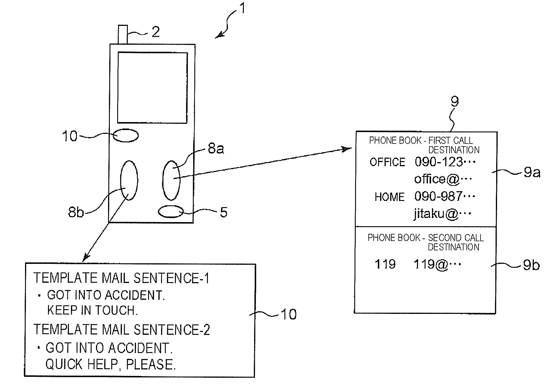
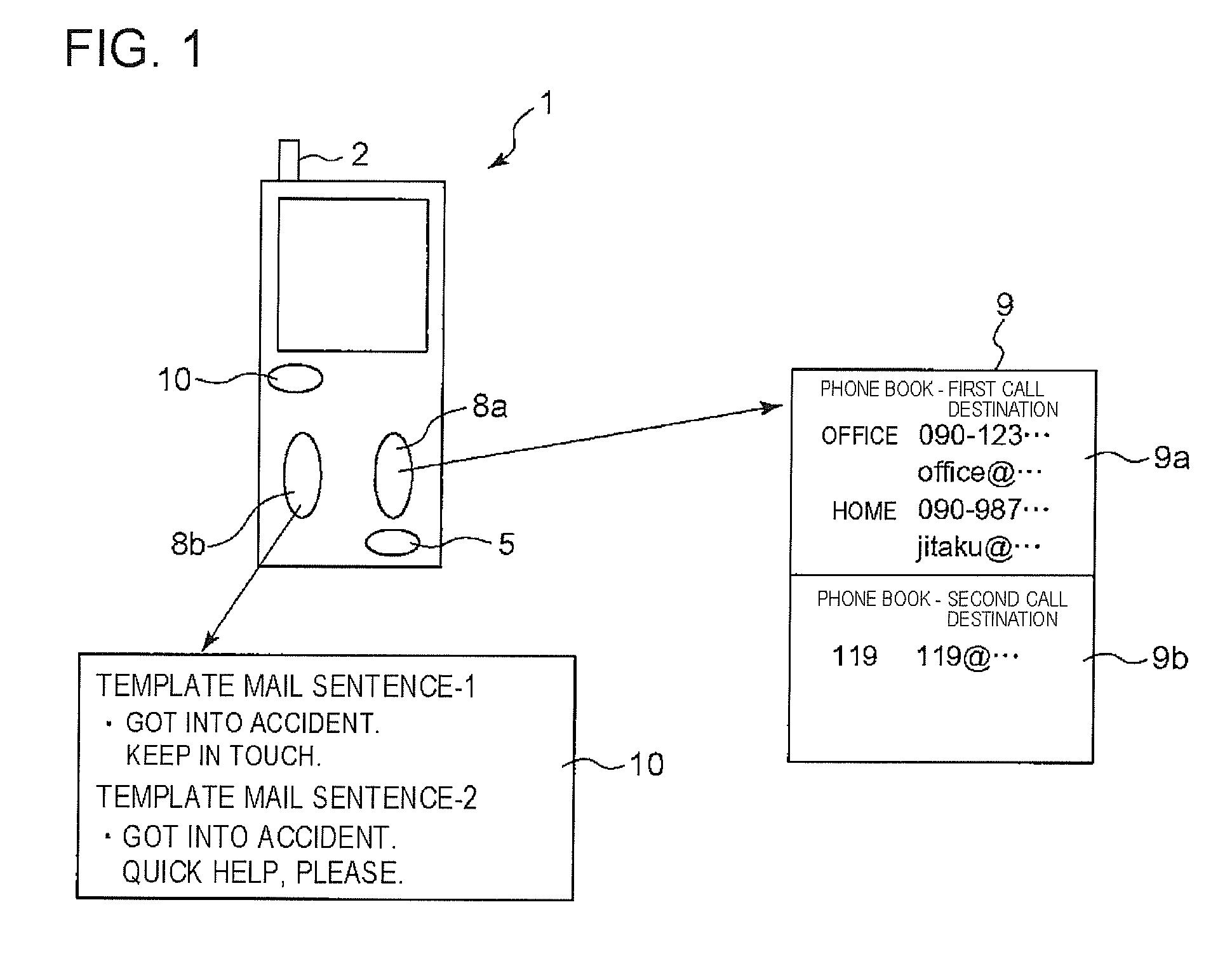
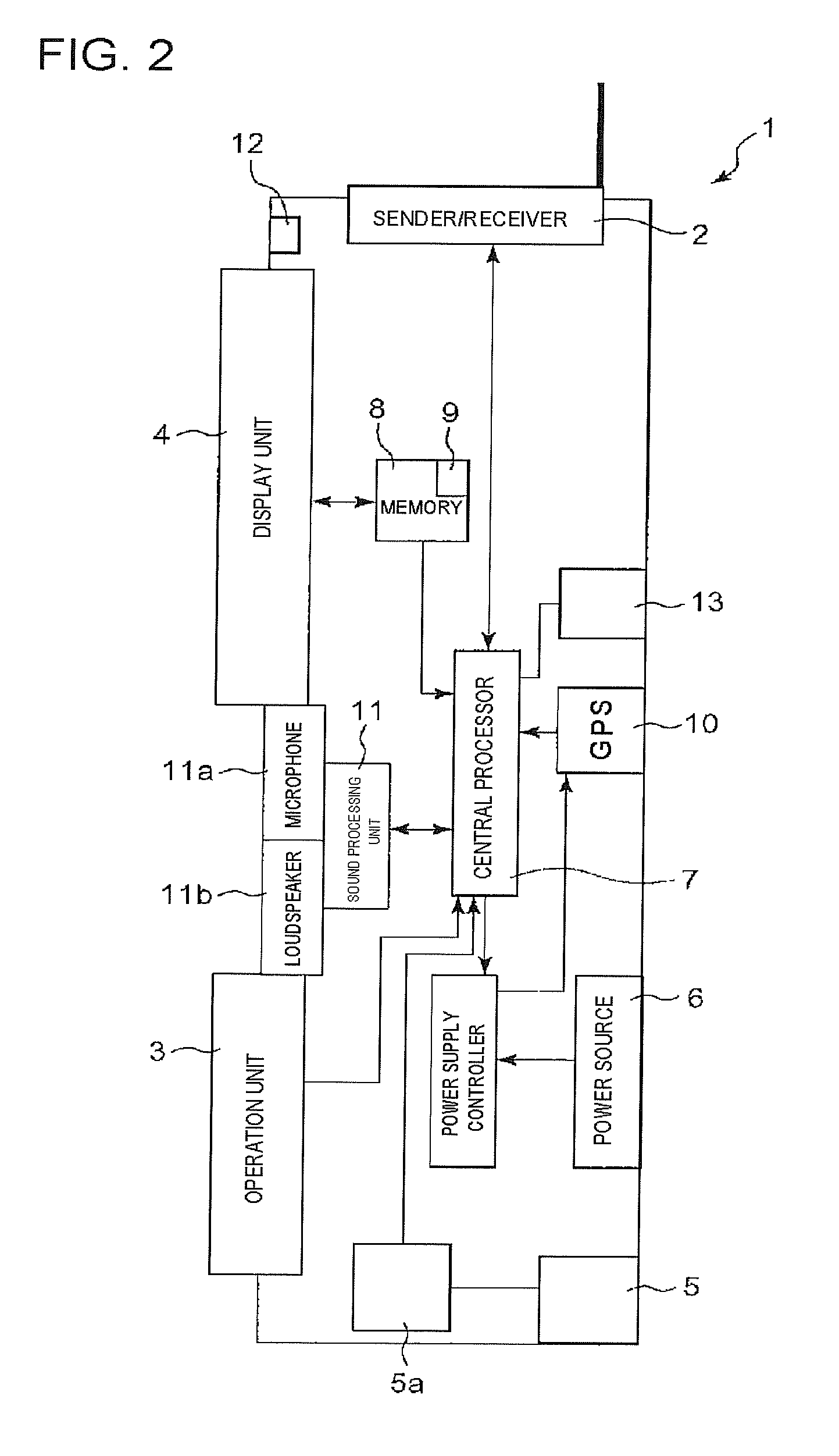
[0047]FIG. 1 is a front elevation schematically showing an appearance of the mobile phone device as the mobile terminal device according to an embodiment of the present invention, FIG. 2 is a block circuit diagram of the mobile phone device as the mobile terminal device according to an embodiment of the present invention, FIG. 3 is a flow chart showing processing operations of a program allowing execution of an emergency rescue method using a mobile terminal device according to an embodiment of the present invention; FIG. 4 is a schematic drawing of the entire configuration of an emergency rescue call system according to an embodiment of the present invention; ...


PUM


Abstract

Disclosed is an emergency rescue system comprising a mobile terminal device and a control center. The mobile terminal device includes: a sender unit capable of sending an electrical mail; an abnormality sensor which detects an abnormality in an outer environment; a GPS receiver which generates GPS positional information; and a control unit which judges whether a level of sensing of the abnormality sensed by the abnormality sensor is not smaller than a predetermined threshold value. The control center judges a state of accident based on both a satellite image and the GPS positional information attached to the template mail sentence received from the mobile terminal device.

Description

[0001]This application is based on Japanese patent application No. 2007-090178 filed Mar. 30, 2007, the content of which is incorporated herein by reference.BACKGROUND[0002]1. Technical Field[0003]The present invention relates to a system, method, mobile phone device and computer program product for emergency rescue.[0004]2. Related Art[0005]In general traffic accident, and in case of encounter with debris flow, flood damage and so forth, one may not make a contact even if he or she had a waterproof mobile phone device, due to the following reasons: 1) the sufferer may not be in a state capable of making a contact (seriously damaged, for example), even if he or she should have a mobile phone device; 2) the sufferer may be confused enough to lose an idea of using a mobile phone device; and 3) the sufferer may not know where the mobile phone device is, even if he or she should have it.[0006]In these situations, the sufferer might be rescued if he or she could be able to make a contact...

Claims


Application Information

Patent Timeline
IPC IPC(8): H04M11/04H04W4/90
CPCG08B17/00G08B21/0446G08B21/08G08B25/001G08B25/005H04M1/72538H04M11/04H04W4/22H04W76/007G08B25/016H04W76/50H04W4/90H04M1/72421
Inventor SHIMANUKI, MASAHIROAMANO, NAOYUKIOWAI, TORU
Owner NEC CORP
Why Eureka
Try Eureka