Load apparatus

a technology of loading apparatus and loading plate, which is applied in the direction of instruments, applications, person identification, etc., can solve the problems of inability to provide an evaluation of bone strength, invasiveness, and difficult quantitative diagnosis of bone strength by means of x-ray photography

Inactive Publication Date: 2008-10-02
HITACHI LTD
View PDF2 Cites 17 Cited by
  • Summary
  • Abstract
  • Description
  • Claims
  • Application Information

AI Technical Summary

Benefits of technology

[0010]The present invention was conceived in view of the above-described circumstances, and ad

Problems solved by technology

The evaluation of bone formation and bone union depends largely on X-ray photography, but quantitatively diagnosing bone strength by means of X-ray photography is very difficult.
However, this method, which requires an extraction operation for obtaining a sample bone, is invasive.
However, these devices are merely means for measuring the amount of bone and cannot provide an evaluati

Method used


Image

  • Load apparatus
  • Load apparatus
  • Load apparatus

Examples


Embodiment Construction

[0020]A preferred embodiment of the present invention will be described in detail with reference to the accompanying drawings.

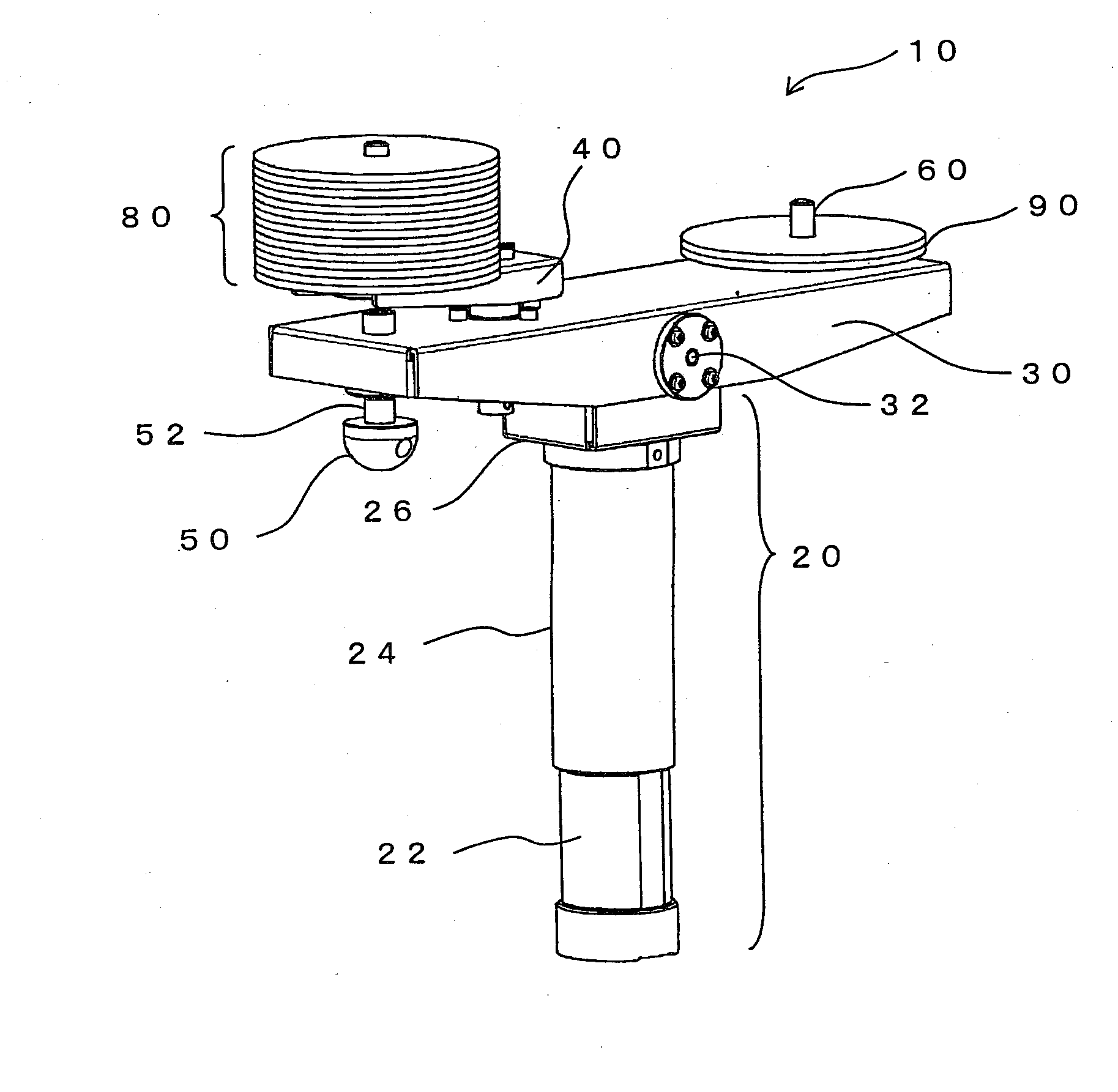
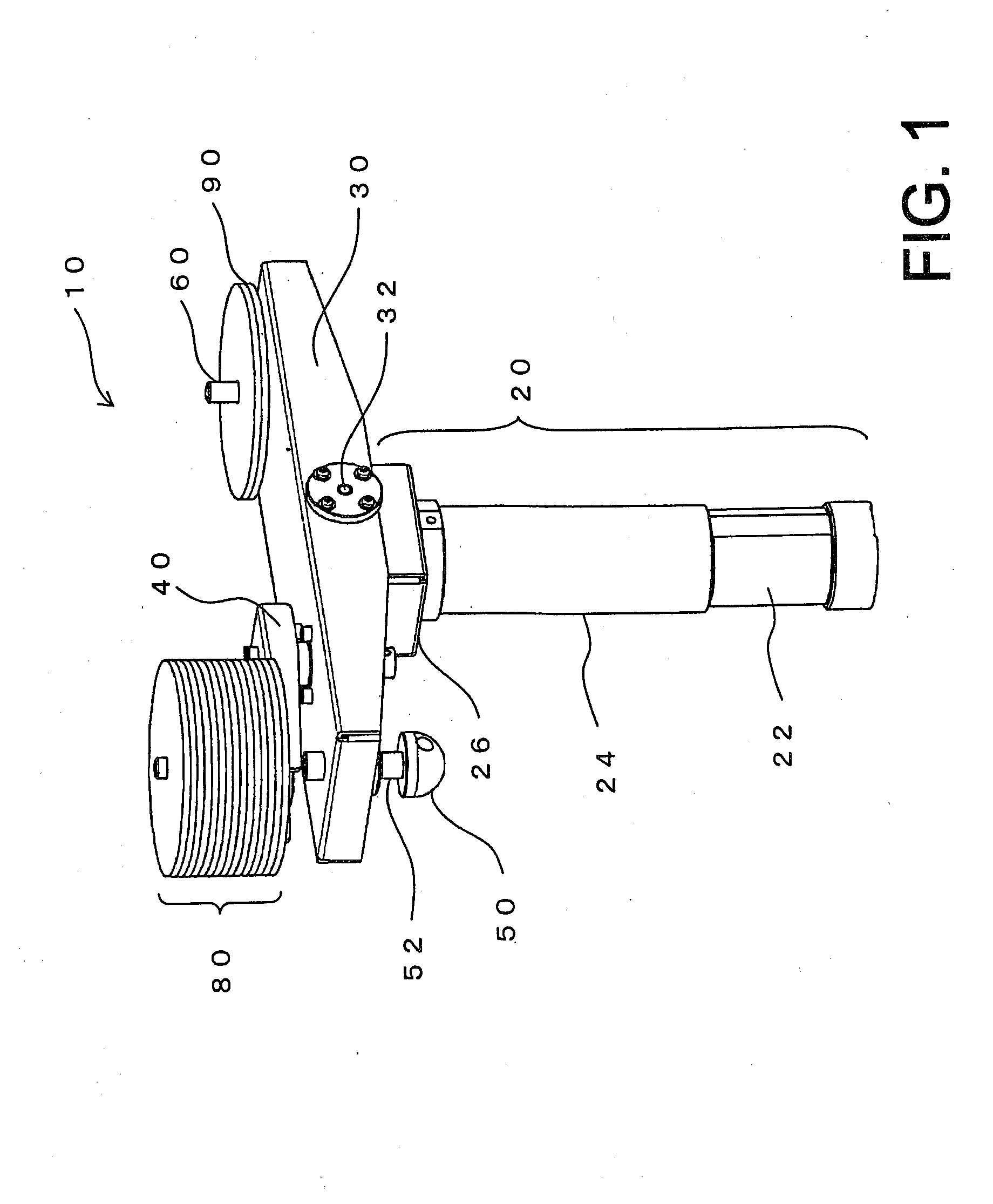
[0021]FIG. 1 is a perspective view showing the entire structure of a preferred embodiment of a load apparatus according to the present invention. Referring to FIG. 1, a load apparatus 10 includes a support rod 20 which functions as a support member, and an oscillation arm 30 which moves in a seesaw fashion about an oscillation axis 32 which serves as a fulcrum and is supported by the support rod 20.

[0022]The support rod 20 is composed of an internal rod portion 22, an external cylinder portion 24, and an oscillation base 26. The internal rod portion 22 includes, at a bottom thereof, a magnet, which allows the load apparatus 10 to be secured with the support rod 20 standing upright on a base having a metallic plate, for example. The external cylinder portion 24 can move relative to the internal rod portion 22 along the longitudinal direction thereof. With this...


PUM


Abstract

An oscillation arm moves in a seesaw fashion about an oscillation axis which is supported by a support rod and which serves as a fulcrum. A rotation arm and a pressurizer are provided on one end of the oscillation arm. One end of the rotation arm is rotatably attached to the oscillation arm, and a load weight is placed on the other end of the rotation arm. By rotating the rotation arm, the magnitude of a force to be applied by the load weight to the pressurizer is adjusted. More specifically, by displacing the load weight to a predetermined position by rotation and then causing the load weight to stop at this position, a static load corresponding to the rotation angle can be applied to the pressurizer. Further, by causing the load weight to perform rotational motion, the magnitude of the force to be applied to the pressurizer is periodically varied, so that a load which varies periodically can be applied to hard tissue.

Description

BACKGROUND[0001]1. Technical Field[0002]The present invention relates to a load apparatus which applies a load to hard tissue such as a bone.[0003]2. Related Art[0004]Simple quantitative measurement of mechanical characteristics such as bone strength is desired for diagnosing bone metabolic diseases such as osteoporosis, for judging fracture risk, and for quantitatively diagnosing bone union after treatment of bone fracture.[0005]The evaluation of bone formation and bone union depends largely on X-ray photography, but quantitatively diagnosing bone strength by means of X-ray photography is very difficult. As a related-art method of measuring bone strength, there is known a strength test of a sample bone of a measurement target. However, this method, which requires an extraction operation for obtaining a sample bone, is invasive. A method of measuring amount of bone and bone density has employed devices such as general-purpose X-ray CT and DXA (dual-energy X-ray absorptiometry) devic...

Claims


Application Information

Patent Timeline
IPC IPC(8): A61B5/05A61B5/103
CPCA61B5/4504A61B8/0875A61B8/485G01N3/32G01N2203/0016
Inventor MINAGAWA, EIICHISAKAI, RYOICHIOGAWA, KOJI
Owner HITACHI LTD
Why Eureka
Try Eureka