Modular connector and method

a technology of connectors and modules, applied in the direction of screw threaded joints, borehole/well accessories, mechanical equipment, etc., can solve the problems of not providing electrical signals to wdp connectors, no known connectors are disclosed for connecting auxiliary flowlines, and existing systems

Active Publication Date: 2008-10-09
SCHLUMBERGER TECH CORP
View PDF77 Cites 83 Cited by
  • Summary
  • Abstract
  • Description
  • Claims
  • Application Information

AI Technical Summary

Benefits of technology

[0021]According to another aspect of the disclosure, a system for drilling a well bore is disclosed. The system includes a drill string for providing a flow of drilling fluid from the surface, a formation testing tool having a first end operatively connected to the drill string and a drill bit operatively connected to a second end of the tool wherein the drill bit receives drilling fluid from the drill string through the formation testing tool. The formation testing tool includes a plurality of modules that each include at least one flowline and a drilling fluid passageway. A first of the plurality of modules is operatively connectable to a first end or a second end of a second of the plurality of modules, thereby allowing transmission of the fluid in the flowline and the drilling fluid passageway between the first and second modules.

Problems solved by technology

A challenge is therefore to maintain a workable tool length (e.g. 30 feet) while performing the necessary fluid and electrical transfers between modules of the tool.
Despite advances in sampling and testing capabilities in downhole tools, existing systems—particularly “while drilling” systems—are often limited to solutions for transferring electrical signals across tools or tool modules.
Such WDP connectors are not known to provide for the transfer of electrical signals between the connected tubular members.
However, no known connectors are disclosed for connecting auxiliary flowlines that extend through and terminate at or near opposing ends of connected wellbore tubulars, or for facilitating a connection between connected components.
Moreover, known connectors or connector systems have not been faced with the additional challenges of drilling tools which involve drill collar, drilling mud, space limitation and harsh drilling issues.

Method used


Image

  • Modular connector and method
  • Modular connector and method
  • Modular connector and method

Examples


Embodiment Construction

[0047]The present disclosure provides a connector and modular system that allows fluid as well as electrical signals to be transferred between nearby tools or modules while maintaining standard drilling operations. Thus, e.g., by utilizing the present disclosure, two LWD or wireline tools or modules can be connected for fluid (hydraulic) and electrical communication therebetween. The connector is adaptable for placement anywhere on a downhole tool string where such communication is needed.

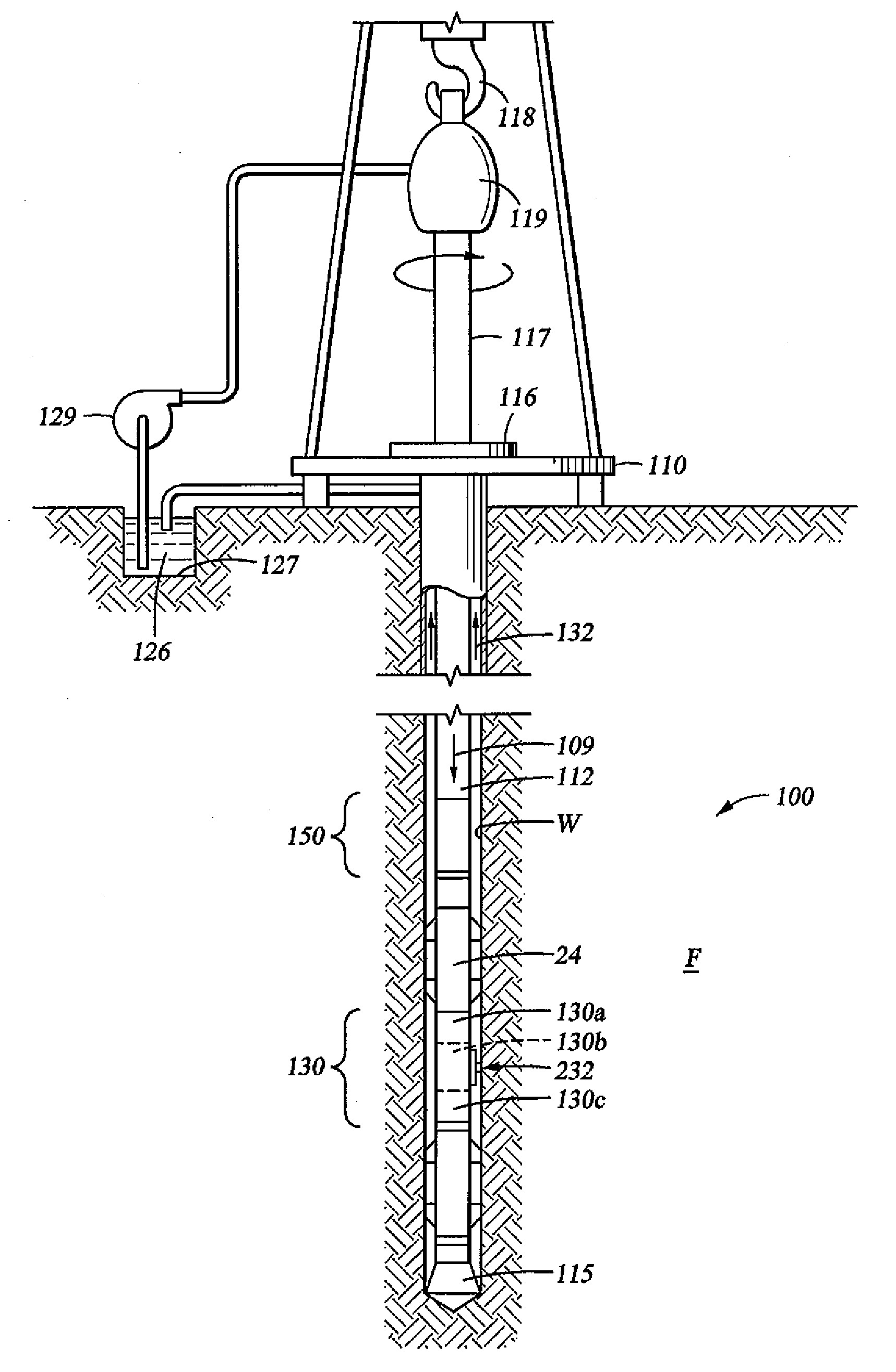
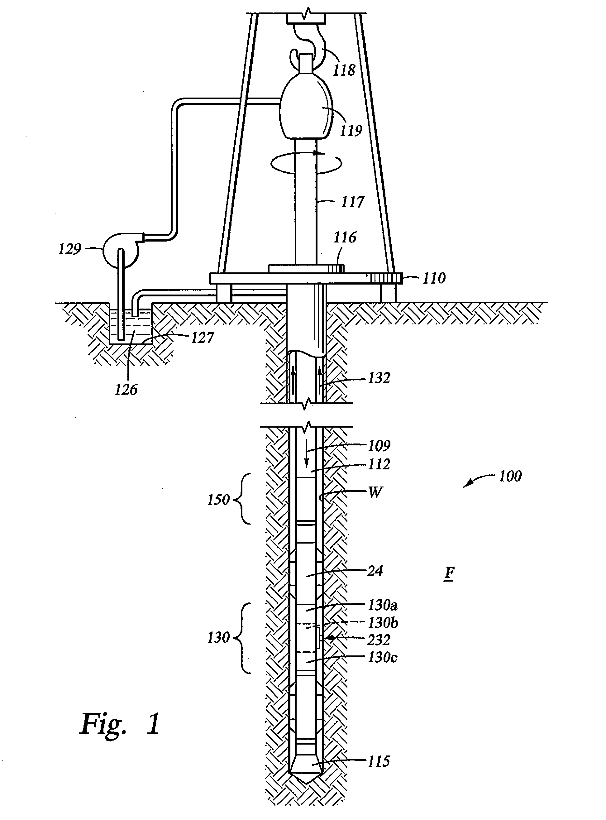
[0048]FIG. 1 illustrates a conventional drilling rig and drill string in which the present disclosure can be utilized to advantage. A land-based platform and derrick assembly 110 are positioned over a wellbore W penetrating a subsurface formation F. In the illustrated embodiment, the wellbore W is formed by rotary drilling in a manner that is well known. Those of ordinary skill in the art given the benefit of this disclosure will appreciate, however, that the present disclosure also finds applicati...


PUM


Abstract

A modular tool for use in subterranean formations includes a first module, a second module and one or more connectors for connecting the first and second modules. In particular, the first module includes a first collar that at least partially defines an exterior of the tool and that includes a first engagement mechanism at a first end of the collar and a second engagement mechanism at a second end of the collar. The first module also includes a fluid passageway for passing drilling fluid therethrough. The second module has a similar configuration as includes similar architecture. The one or more connectors facilitate the connection of at least one flowline fluidly connected to an exterior of the tool, and an electrical pathway for transmitting power and/or data between the modules.

Description

CROSS REFERENCE TO RELATED APPLICATIONS[0001]This application is a continuation-in-part application of co-pending U.S. patent application Ser. No. 11 / 160,240, filed Jun. 15, 2005, the content of which is incorporated herein by reference for all purposes.BACKGROUND[0002]1. Field of the Invention[0003]The present invention relates to the downhole tools for use in subterranean formation evaluation and, more specifically, to the modularity of components in a downhole tool for use in a while-drilling environment.[0004]2. Background of the Related Art[0005]Wellbores (also known as boreholes) are drilled for hydrocarbon prospecting and production. It is often desirable to perform various evaluations of the formations penetrated by a wellbore during drilling operations, such as during periods when actual drilling has temporarily stopped. In some cases, the drill string may be provided with one or more drilling tools to test and / or sample the surrounding formation. In other cases, the drill ...

Claims


Application Information

Patent Timeline
Patent Type & Authority Applications(United States)
IPC IPC(8): E21B49/08
CPCE21B17/02E21B17/028F16L39/04E21B49/10F16L15/02E21B17/18E21B47/13E21B49/08
Inventor PARTOUCHE, ASHERS
Owner SCHLUMBERGER TECH CORP
Why Eureka
Try Eureka