Liquid chromatograph

a liquid chromatograph and chromatograph technology, applied in the field of liquid chromatographs, can solve the problems of reducing separation performance, difficult to achieve highly sensitive analysis, complicated change in flow passage configuration, etc., and achieve the effect of improving analytical reproducibility and promoting solvent mixing

Active Publication Date: 2008-10-09
SHIMADZU CORP
View PDF1 Cites 11 Cited by
  • Summary
  • Abstract
  • Description
  • Claims
  • Application Information

AI Technical Summary

Benefits of technology

[0009]It is an object of the present invention to provide a liquid chromatograph which uses a mixture of a plurality of kinds of solvents as a mobile phase and which enables analysis to be carried out without causing a problem even when the mobile phase is sent at any flow rate within a wide range.
[0017]In the liquid chromatograph according to the present invention, flow passage switching is carried out so that, in the case of normal analysis, a normal analysis flow passage is formed by connecting the mobile-phase-sending-unit, the second mixer, the sample injection portion, the analysis column and the detector in this order, and in the case of sample concentration, a concentration flow passage is formed by connecting the concentration liquid sending unit, the sample injection portion and the trapping column, and in the case of concentration analysis, a concentration analysis flow passage is formed by connecting the mobile-phase-sending-unit, the first mixer, the trapping column, the analysis column and the detector in this order, and further the flow rate of a mobile phase is made smaller in concentration analysis than in normal analysis. Therefore, in both cases of normal analysis using a mobile phase sent at a relatively large flow rate and concentration analysis using a mobile phase sent at a relatively small flow rate, it is possible to promote the mixing of solvents using a mixer having a capacity suitable for the flow rate of a mobile phase. This makes it possible to sufficiently mix solvents irrespective of the flow rate of a mobile phase and therefore to improve analytical reproducibility without causing a delay in sending of the mobile phase.

Problems solved by technology

At this time, when the amount of the sample injected from the sample injection portion is large, a sample band in the analysis column is broadened by the action of a solvent contained in the sample, thereby reducing separation performance and making it impossible to achieve highly-sensitive analysis.
However, in the case of analysis of a dilute sample, it is necessary to increase the absolute mass of the sample to achieve sufficient sensitivity, and therefore there is a case where a large amount of sample must be injected from the sample injection portion.
Such a change in flow passage configuration is very complicated and takes much time, and in addition, attention needs to be paid so that leakage of a mobile phase and a dead volume in a flow passage will not occur even after changing a flow passage configuration.
This is because, in a case where a mixer having a capacity of 1 mL is used when a mobile phase is sent at a flow rate of 5 μL / min, the capacity of the mixer is too large for the flow rate of the mobile phase and therefore a delay as long as about 200 minutes occurs.
On the other hand, in a case where a mixer having a capacity of 5 μL is used when a mobile phase is sent at a flow rate of 1 mL / min, the mobile phase cannot be sufficiently mixed.
For this reason, in a case where it is necessary to send a mobile phase at various flow rates in a wide range from a micro flow rate to a conventional flow rate in a single system of a liquid chromatograph, the selection of the capacity of a mixer to be used becomes a problem.

Method used


Image

  • Liquid chromatograph
  • Liquid chromatograph
  • Liquid chromatograph

Examples


Embodiment Construction

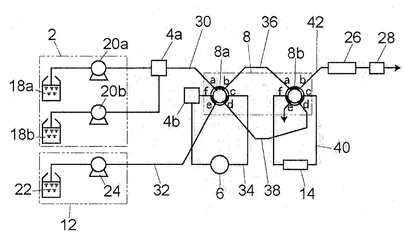
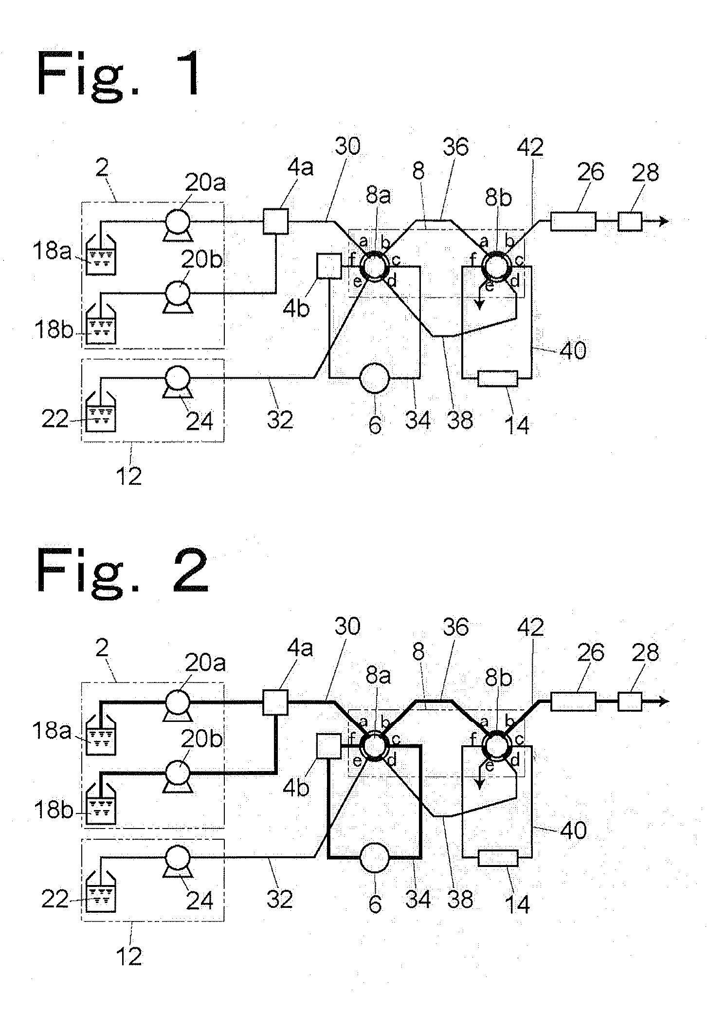
[0022]Hereinafter, a liquid chromatograph according to one embodiment of the present invention will be described. FIG. 1 is a diagram specifically showing the flow passage configuration of the liquid chromatograph according to one embodiment of the present invention.

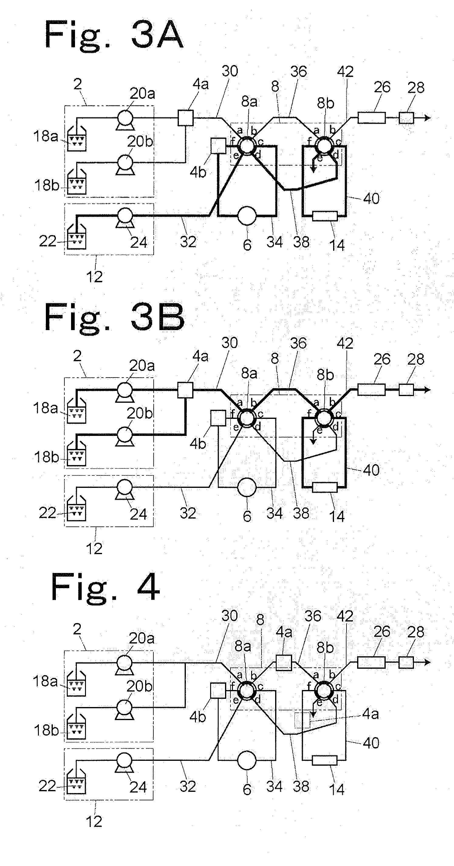
[0023]A flow passage switching mechanism 8 has two first and second flow passage switching valves 8a and 8b as multi-port valves. The flow passage switching valves 8a and 8b are two-position six-port valves each having six ports numbered a to f clockwise. Each of the flow passage switching valves 8a and 8b is set to allow the ports a and b adjacent to each other to be connected to each other, the ports c and d adjacent to each other to be connected to each other, and the ports e and f adjacent to each other to be connected to each other at the same time and to allow, at another timing, the ports a and f adjacent to each other to be connected to each other, the ports b and c adjacent to each other to be connected to each ...


PUM

PropertyMeasurementUnit
flow rateaaaaaaaaaa
flow rateaaaaaaaaaa
flow rateaaaaaaaaaa

Abstract

A liquid chromatograph having a flow passage switching mechanism for switching among a normal analysis flow passage formed by connecting a mobile-phase-sending-unit, a second mixer having a large capacity, a sample injection portion, an analysis column and a detector in this order, a concentration flow passage formed by connecting a concentration liquid sending unit for sending a liquid for transferring a sample to be concentrated, the second mixer, the sample injection portion and a trapping column in this order, and a concentration analysis flow passage formed by connecting the mobile-phase-sending-unit, a first mixer having a smaller capacity than the second mixer, the trapping column, the analysis column and the detector in this order so that any one of the three flow passages is selectively formed, The mobile-phase-sending-unit is set so that the flow rate of a mobile phase becomes smaller when the concentration analysis flow passage is selected than when the normal analysis flow passage is selected.

Description

BACKGROUND OF THE INVENTION[0001]1. Field of the Invention[0002]The present invention relates to a liquid chromatograph having a mobile phase flow passage for sending a mobile phase obtained by mixing a plurality of kinds of solvents with a mixer and used for introducing a sample injected from a sample injection portion into an analysis column. Particularly, the present invention relates to a liquid chromatograph having a trapping column for concentrating a dilute sample and allowing the sample to be analyzed in a concentrated state.[0003]2. Description of the Related Art[0004]Generally, in the case of analysis using a high-performance liquid chromatograph, a sample is injected into an analysis flow passage from a sample injection portion, and then transferred into an analysis column by a mobile phase sent by a liquid sending pump, and then separated into individual components by the analysis column. At this time, when the amount of the sample injected from the sample injection port...

Claims


Application Information

Patent Timeline
Patent Type & Authority Applications(United States)
IPC IPC(8): B01D15/08
CPCB01D15/166G01N30/08G01N30/468G01N2030/027G01N2030/085
Inventor IWATA, YOSUKE
Owner SHIMADZU CORP
Why Eureka
Try Eureka