High frequency wave glass antenna for an automobile and window glass sheet for an automobile with the same

Inactive Publication Date: 2008-10-09
ASAHI GLASS CO LTD
View PDF7 Cites 6 Cited by
  • Summary
  • Abstract
  • Description
  • Claims
  • Application Information

AI Technical Summary

Benefits of technology

[0013]It is easy to mount the glass antenna according to the present invention since the glass antenna has a simple structure as a whole. The glass antenna according to the present invention is optimal as a high

Problems solved by technology

The prior art antenna has a complicated structure as a whole, which causes a problem in that it is not easy to mount the antenna.
In a case where an antenna including one or plural antenna conductors is used as a high frequency wave glass antenna for an automobile in use for receiving a digital terrestrial television broadcast in Japan

Method used


Image

  • High frequency wave glass antenna for an automobile and window glass sheet for an automobile with the same
  • High frequency wave glass antenna for an automobile and window glass sheet for an automobile with the same
  • High frequency wave glass antenna for an automobile and window glass sheet for an automobile with the same

Examples


Example

EXAMPLE 1

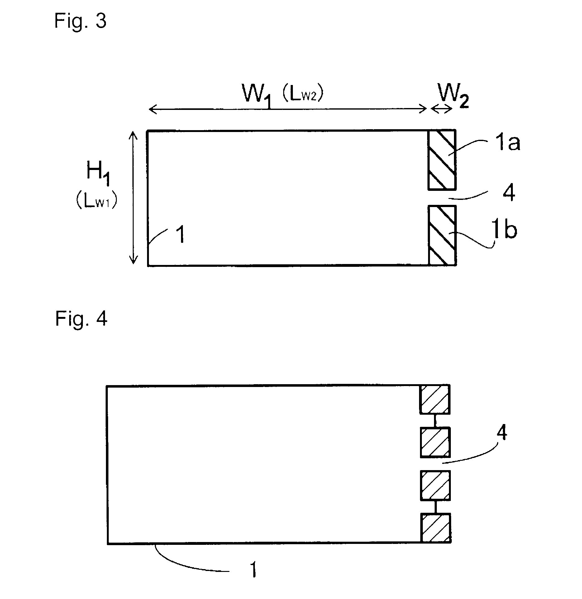
[0076]It is assumed that a square glass substrate forms a rear window glass sheet. The high frequency wave glass antenna for an automobile is formed by disposing the antenna conductor 1 shown in FIG. 3 at a central portion of the glass substrate on one of the opposed surfaces of the glass substrate, which is supposed to be positioned on the car-interior-side. It is assumed that no other conductor than the antenna conductor 1 is disposed on the glass substrate.

[0077]In accordance with the FDTD method (Finite Difference Time Domain method), the return loss was calculated with the conductor width W2 being changed in a range from 0.8 to 40 mm. The calculation on the return loss was made at every 1 MHz in a frequency band of 470 to 770 MHz. The calculated values of the respective portions are listed below. FIG. 13 shows a characteristic graph which represents the minimum values of the return loss by the vertical axis and the conductor width W2 by the horizontal axis, based on th...

Example

EXAMPLE 2

[0078]The return loss was calculated with (LW2 / LW1) being changed (in other words, with (W1 / H1) being changed) under the same conditions as those in Example 1 except for the conditions listed below. The calculation method was the same as that in Example 1. (LW2 / LW1) was calculated at twelve points of 0.01, 0.05, 0.11, 0.25, 0.33, 0.50, 0.80, 1.00, 3.00, 5.00, 9.00 and 11.00. FIG. 14 shows a characteristic graph which represents the minimum values of the return loss by the vertical axis and (LW2 / LW1) by the horizontal axis.

[0079]FIGS. 15 to 17, based on which FIG. 14 is prepared, show return loss-frequency characteristics for respective values of (LW2 / LW1). FIG. 15 shows 0.01, 0.05, 0.11 and 0.25 as the values of (LW2 / LW1). FIG. 16 shows 0.33, 0.50, 0.80 and 1.00 as the values of (LW2 / LW1). FIG. 17 shows 3.00, 5.00, 9.00 and 11.00 as the values of (LW2 / LW1).

W220 mmGap of discontinuity 4 5 mm

Example

EXAMPLE 3

[0080]The return loss was calculated at two points of 3.00 is and 11.00 for (LW2 / LW1) under the same conditions as those in Example 2 except that the discontinuity 4 has a gap of 1 mm.

[0081]When (LW2 / LW1) was 3.00, the return low had a minimum value of −7.75 dB in both of Example 2 and Example 3. When (LW2 / LW1) was 11.00, the return loss had a minimum value of −1.07 dB in both of Example 2 and Example 3. This reveals that there is no change in the value of the return loss in both of a case where the discontinuity 4 has a gap of 1 mm and a case where the discontinuity 4 has a gap of 5 mm.


PUM


Abstract

A high frequency wave glass antenna for an automobile includes an antenna conductor adapted to be disposed in or on an automobile window glass sheet, the antenna conductor being formed in such a loop shape that a portion of the loop shape is cut out by a length to dispose a discontinuity, both ends of the discontinuity or portions of the antenna conductor close to the discontinuity serving as feeding points, and a portion of the antenna conductor with the discontinuity disposed therein or a portion of the antenna conductor close to the discontinuity having a conductor width of 8.0 to 40 mm.

Description

BACKGROUND OF THE INVENTION[0001]1. FIELD OF THE INVENTION[0002]The present invention relates to a high frequency wave glass antenna for an automobile, which is appropriate to receive a digital terrestrial television broadcast in Japan (470 to 770 MHz), a UHF band analog television broadcast in Japan (470 to 770 MHz), or a US digital television broadcast (698 to 806 MHz). The present invention also relates to a window glass sheet for an automobile with the high frequency wave glass antenna.[0003]2. DISCUSSION OF BACKGROUND[0004]Referring to FIG. 20, as a high frequency wave glass antenna for an automobile in use for receiving a digital terrestrial television broadcast in Japan, there has been used one that comprises a loop-shaped element 30 on a window glass sheet and a feeding point 31 disposed to the loop-shaped element 30 as disclosed in, e.g. JP-A-2006-25452.[0005]This prior art antenna is a ground antenna, which needs to have a grounded element for connection therewith. The gro...

Claims


Application Information

Patent Timeline
IPC IPC(8): H01Q1/32
CPCH01Q1/1271H01Q7/00
Inventor KAGAYA, OSAMUOSHIMA, KIYOSHIIKAWA, KOJI
Owner ASAHI GLASS CO LTD
Why Eureka
Try Eureka