Small, narrow profile multiband antenna

a multi-band antenna, small technology, applied in the direction of resonant antennas, helical antennas, non-resonant long antennas, etc., can solve the problems of inconvenient detection, inconvenient detection of sensors used for military purposes, and large antennas known in the art, etc., to achieve the effect of defeating the purpos

Active Publication Date: 2008-10-09
SHAKESPEARE CO
View PDF15 Cites 20 Cited by
  • Summary
  • Abstract
  • Description
  • Claims
  • Application Information

AI Technical Summary

Benefits of technology

[0005]In light of the foregoing, it is a first aspect of the present invention to provide a small, narrow profile multiband antenna.

Problems solved by technology

For example, sensors used for military purposes must be inconspicuous and not easily detected.
Unfortunately, such antennas known in the art can be quite sizeable and easily detected, thereby defeating their purpose.

Method used


Image

  • Small, narrow profile multiband antenna
  • Small, narrow profile multiband antenna
  • Small, narrow profile multiband antenna

Examples


Embodiment Construction

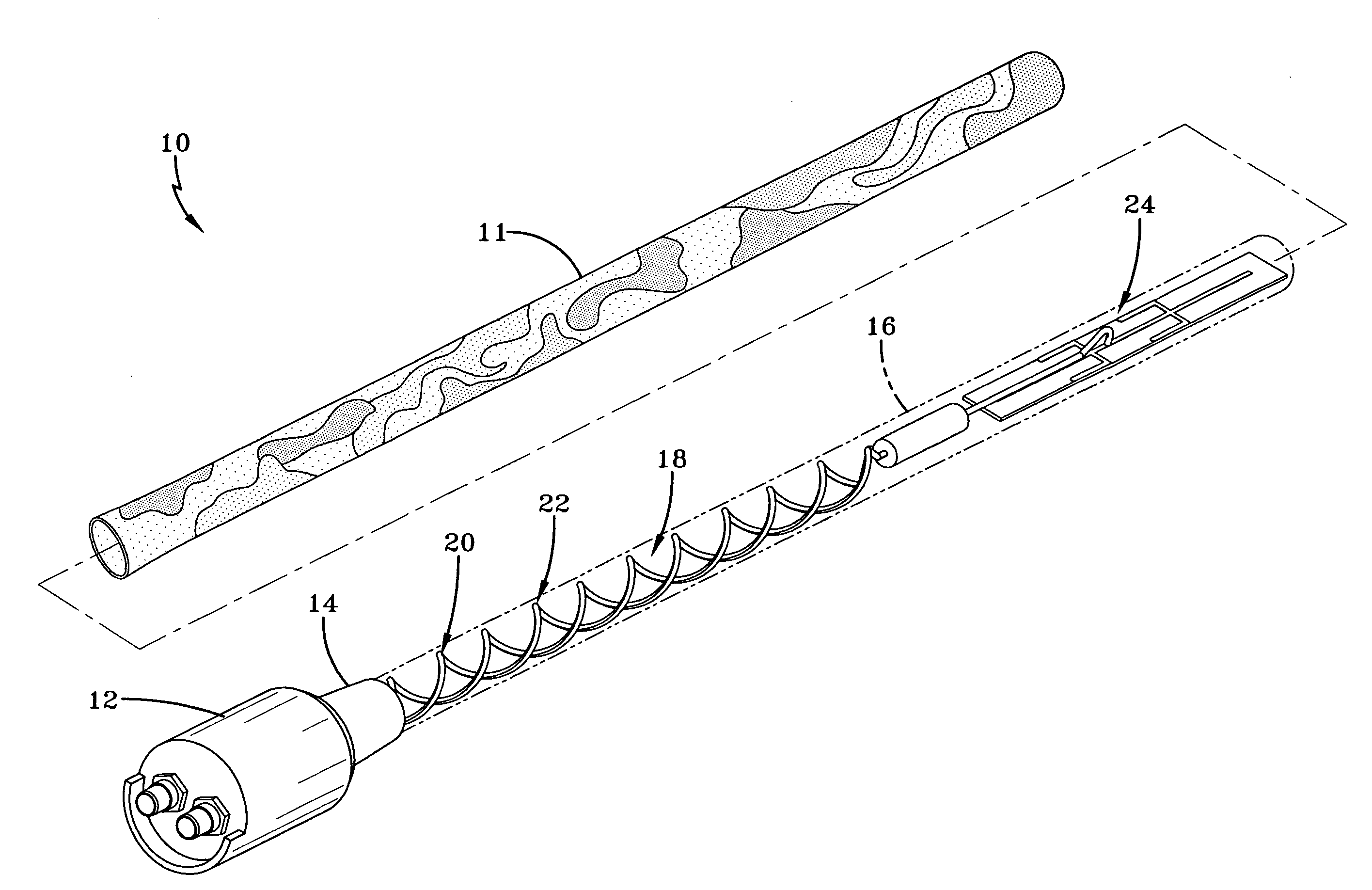
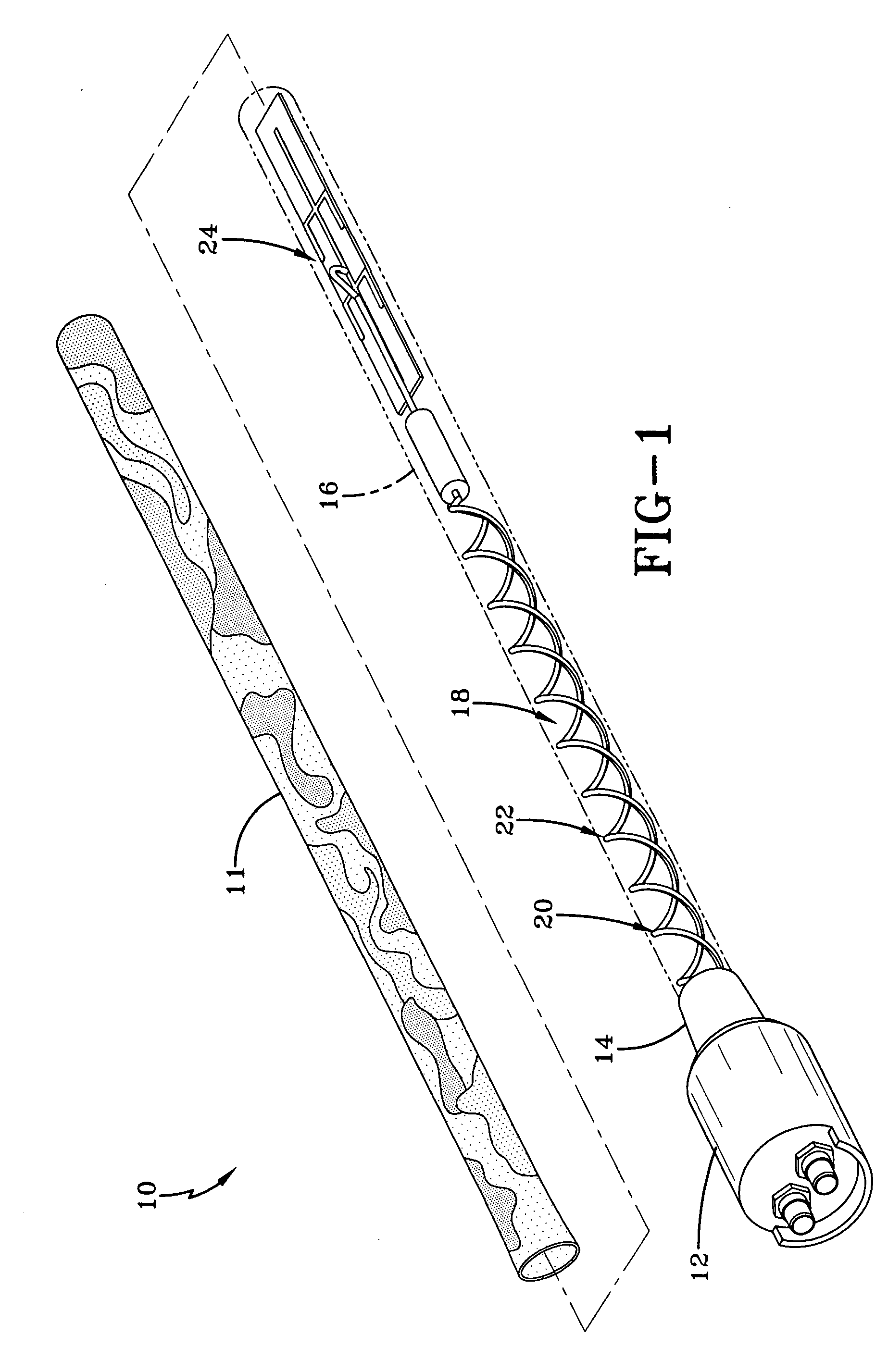
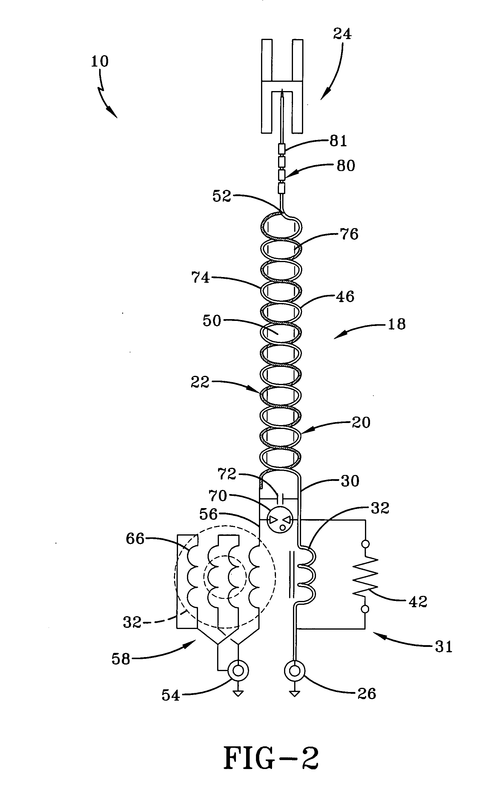
[0019]Referring now to the drawings, and particularly to FIGS. 1 and 2, it can be seen that a multiband antenna system according to the concepts of the present invention is designated generally by the numeral 10. The antenna system may be used with ground sensors, other types of sensors, or any other device that requires the transmission and the reception of wireless signals. As will become apparent as the description proceeds, the antenna system 10 is constructed in such a manner so as to provide a relatively small and narrow profile so that the antenna system is not easily detected. Indeed, the antenna system can be constructed in such a manner to blend with the terrain in which the associated sensor is to be located. For example, the antenna system 10 can be provided with brown / green coloring so as to allow it to be placed in fields, or the antenna system 10 can be constructed to match rock textures in a selected region. To allow a rapid change of the type of camouflage, a radio ...


PUM


Abstract

A multiband antenna system includes a helical antenna having a first leg and a second leg wherein the first leg consists of a coaxial conductor. The multiband antenna also includes an antenna sub-system coupled to the helical antenna wherein the coaxial conductor feeds the antenna sub-system. A radome encloses components of the antenna system, and the radome may be covered by a radio-frequency transparent sock for concealment purposes.

Description

TECHNICAL FIELD[0001]The present invention is generally directed to multiband antennas. In particular, the present invention is directed to a multiband antenna which is small and provides a narrow profile. Specifically, the present invention is directed to a multiband antenna which provides good isolation properties and is small enough for use with an unmanned ground sensor.BACKGROUND ART[0002]Currently, unmanned ground sensors are positioned in remote locations. The sensors collect information and data related to weather and ground conditions. And, these ground sensors can detect physical activity such as movement of vehicles, individuals and animals in a defined area. With appropriate antenna systems, these sensors are also capable of transmitting the collected information to a centralized location by transmitting signals to a nearby ground station, over-flying aircraft, or even satellites. The antenna system functions as part of the overall sensor to detect the aforementioned mov...

Claims


Application Information

Patent Timeline
Patent Type & Authority Applications(United States)
IPC IPC(8): H01Q1/36H01Q5/00H01Q5/40
CPCH01Q1/362H01Q1/44H01Q1/50H01Q5/40H01Q11/08H01Q21/30H01Q5/00
Inventor MARTEK, GARY A.FULMER, LEONMAYNARD, JOHNJARMAN, HENRY
Owner SHAKESPEARE CO
Why Eureka
Try Eureka