Recriprocating Compressor

a compressor and lateral pressure technology, applied in the direction of positive displacement liquid engines, piston pumps, lighting and heating apparatus, etc., can solve the problems of difficult suppression of vibrations produced, and achieve the effects of reducing lateral pressure of pistons, reducing energy consumption, and reducing vibrations

Inactive Publication Date: 2008-10-09
PANASONIC CORP
View PDF8 Cites 7 Cited by
  • Summary
  • Abstract
  • Description
  • Claims
  • Application Information

AI Technical Summary

Benefits of technology

[0010]The present invention provides reliable reciprocating compressors that work more efficiently in energy consumption and produce smaller vibrations. The reciprocating compressor of the present invention includes a cylinder and a balancing weight. The cylinder is placed offset such that the both axis lines of the cylinder and a main shaft will not cross each other, and the balancing weight is placed such that the center of gravity thereof is positioned generally opposite the center of an eccentric section with respect to the axial line of the main shaft and deviated along the rotating direction from the place just opposite to the center of the eccentric section. The foregoing structure allows reducing lateral pressure of the piston, so that the reliability and efficiency of the reciprocating compressor can be increased. The structure also allows efficiently canceling unbalancing-force produced by the motions of the piston, connecting rod, and the eccentric section more effectively with the motion force of the balancing weight, so that the vibrations of the reciprocating compressor can be reduced.

Problems solved by technology

However, a greater piston of reciprocating compressors makes it difficult to suppress vibrations produced by reciprocal motion of the piston to a low level.

Method used


Image

  • Recriprocating Compressor
  • Recriprocating Compressor
  • Recriprocating Compressor

Examples


Embodiment Construction

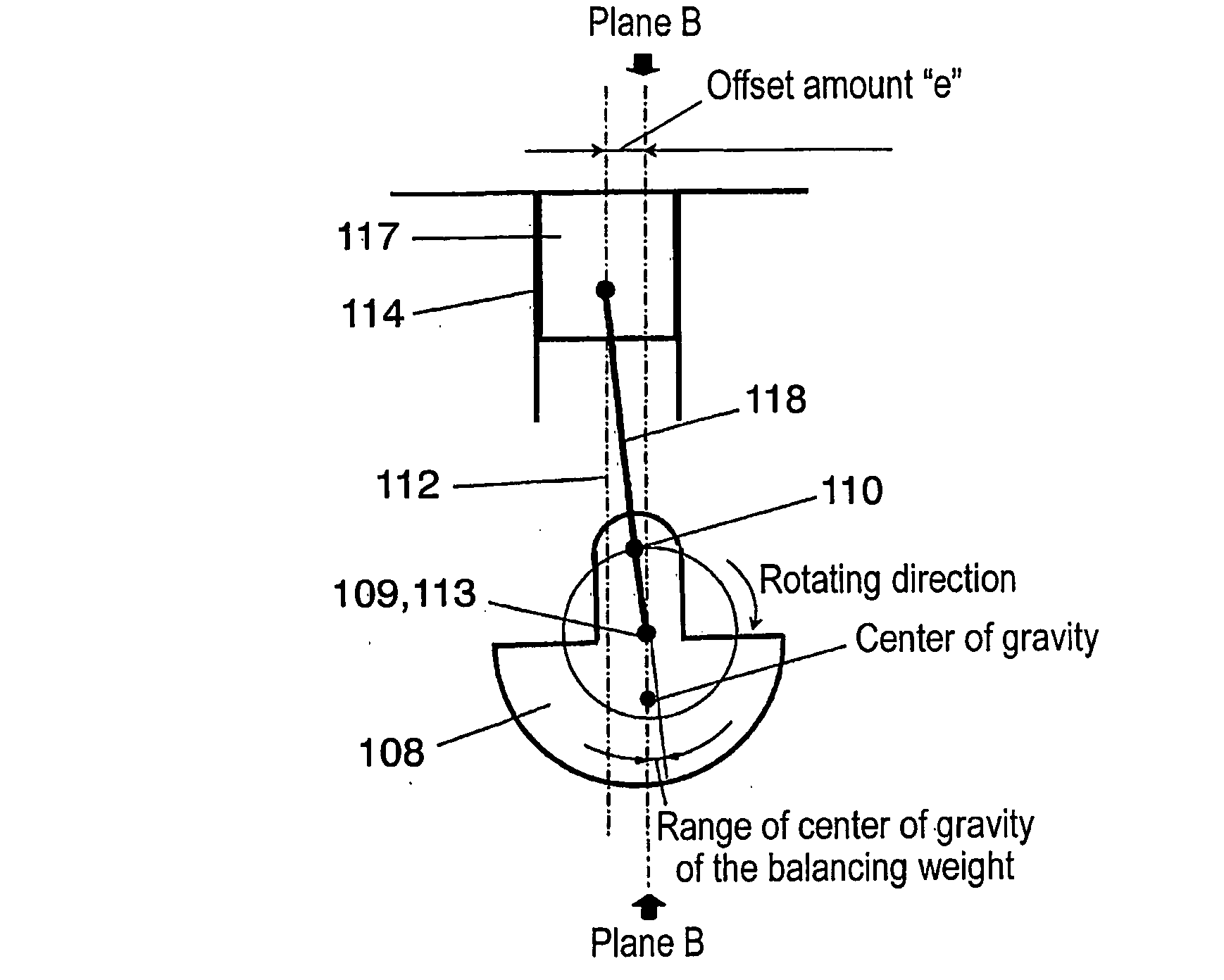
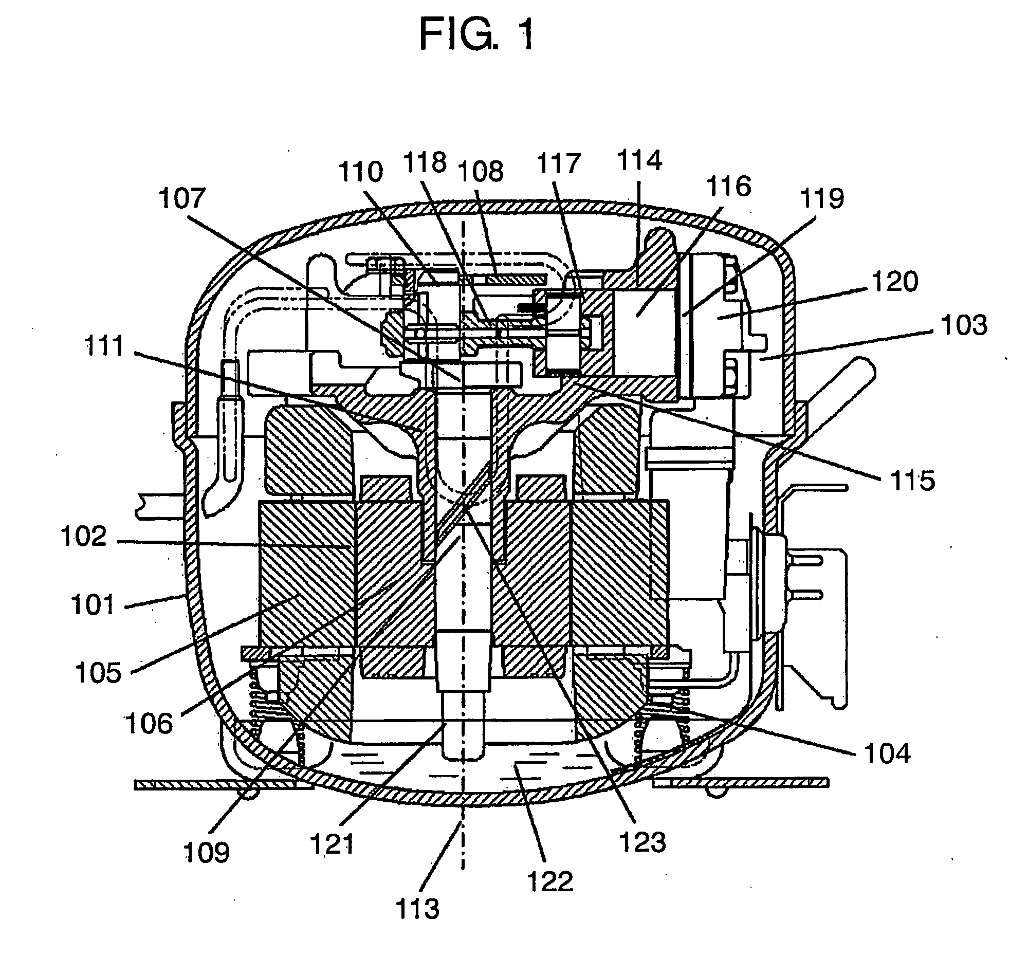
[0017]A reciprocating compressor of the present invention includes a hermetic container which accommodates a compressing element for compressing refrigerant gas. The compressing element comprises the following elements:[0018]a crankshaft generally disposed perpendicularly and having a main shaft and an eccentric section;[0019]a block forming a cylindrical cylinder;[0020]a piston reciprocating in the cylinder;[0021]a connecting rod connecting the eccentric section to the piston; and[0022]a balancing weight for balancing vibrations produced by foregoing elements including at least one of the piston, the connecting rod and the eccentric section.

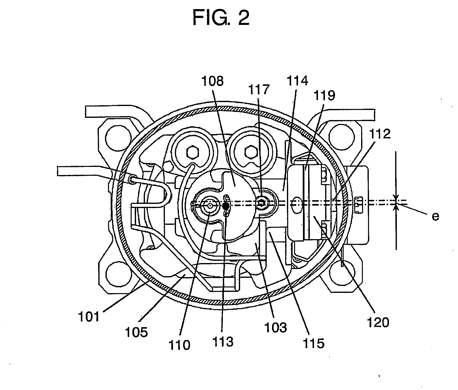
[0023]The cylinder is placed offset such that the axis lines of both the cylinder and the main shaft will not cross each other, and the balancing weight is placed such that the center of gravity thereof is positioned generally opposite the center of the eccentric section with respect to the axial line of the main shaft and deviated along the rot...


PUM


Abstract

A highly reliable reciprocating compressor works efficiently with less energy, and produces smaller vibrations. This reciprocating compressor includes a crankshaft, a block, a piston, a connecting rod, and a balancing weight. The cylinder is placed offset such that an axis line thereof and an axis line of the main shaft do not cross each other. The center of gravity of the balancing weight is placed substantially opposite to the center of the eccentric section with respect to the axis line of the main shaft and deviated along a rotating direction of the main shaft from the place just opposite to the center of the eccentric section. The foregoing construction allows reducing lateral pressure of the piston, thereby increasing the reliability and efficiency of the reciprocating compressor, and allows to cancel unbalancing force produced by motions of the piston, the connecting rod and the eccentric section with motion of the balancing weight.

Description

TECHNICAL FIELD[0001]The present invention relates to how to reduce vibrations produced by reciprocating compressors.BACKGROUND ART[0002]Energy-saving has been increasingly required to home-use refrigerators because of a movement of global environmental protection. In such a climate, refrigerant compressors to be used in the household refrigerators have employed an inverter technique to reduce the number of rotations (rpm), namely this technique can operate the reciprocating compressors at a lower rpm. Refrigerant gas also starts employing R600a gas having a lower greenhouse coefficient. Those technical changes require a greater capacity of a cylinder to be placed in the refrigerant compressors in order to maintain refrigerating effect of the refrigerant. However, a greater piston of reciprocating compressors makes it difficult to suppress vibrations produced by reciprocal motion of the piston to a low level. On the other hand, various measures have been taken for improving the reli...

Claims


Application Information

Patent Timeline
Patent Type & Authority Applications(United States)
IPC IPC(8): F04B9/04F01B9/02
CPCF04B39/0094F16F15/22F16F15/28F04B39/122F04B39/0005F04B39/0022F04B9/045F25B31/00F05B2210/12F05B2210/14F05B2260/96
Inventor KUBOTA, AKIHIKONAGAO, TAKAHIDETSUBOI, KOSUKEKAKIUCHI, TAKASHI
Owner PANASONIC CORP
Why Eureka
Try Eureka