
Method and device for distending a gynecological cavity

a gynecological cavity and tool technology, applied in the field of medical devices, can solve the problems of insufficient space, certain risks associated with it, and may be quite harmful to the patient, and achieve the effect of reducing the risk of infection, and improving the patient's overall health

Active Publication Date: 2008-10-09
HOLOGIC INC
View PDF104 Cites 160 Cited by
  • Summary
  • Abstract
  • Description
  • Claims
  • Application Information

AI Technical Summary

Benefits of technology

[0014]The distension structure could have a loop or two that are independent from the others and that are electronically enabled to provide cautery or loop resection or mechanically enabled to provide grabbing and manipulation tasks while easily converting back to a distension mechanism.

Problems solved by technology

Unfortunately, however, in those instances in which the gynecological cavity in question is the uterine cavity, adequate space does not typically exist naturally.
Although the aforementioned technique of fluid distension is commonly practiced, there are certain risks associated therewith.
For example, because the distending fluid is administered under pressure (which pressure may be as great as 80-100 mm Hg or greater), there is a risk that such fluids may be taken up by a blood vessel in the uterus, i.e., intravasation, which uptake may be quite harmful to the patient.
This risk is particularly great when the fluid distension technique is followed by a procedure in which a blood vessel is cut, such as when an abnormal or undesired tissue located in the uterus is removed or ablated.
Moreover, the above-described technique of fluid distension suffers from additional shortcomings.
Furthermore, the above-described fluid distension technique may become messy, particularly when a liquid is used as the distension fluid, as some of the distension fluid within the uterus may escape proper collection and, instead, may leak from the patient to the surrounding environment.

Method used


Image

  • Method and device for distending a gynecological cavity
  • Method and device for distending a gynecological cavity
  • Method and device for distending a gynecological cavity

Examples


Embodiment Construction

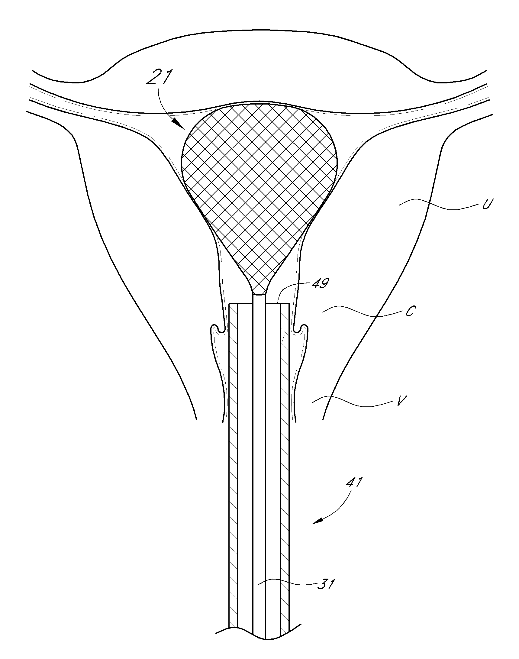
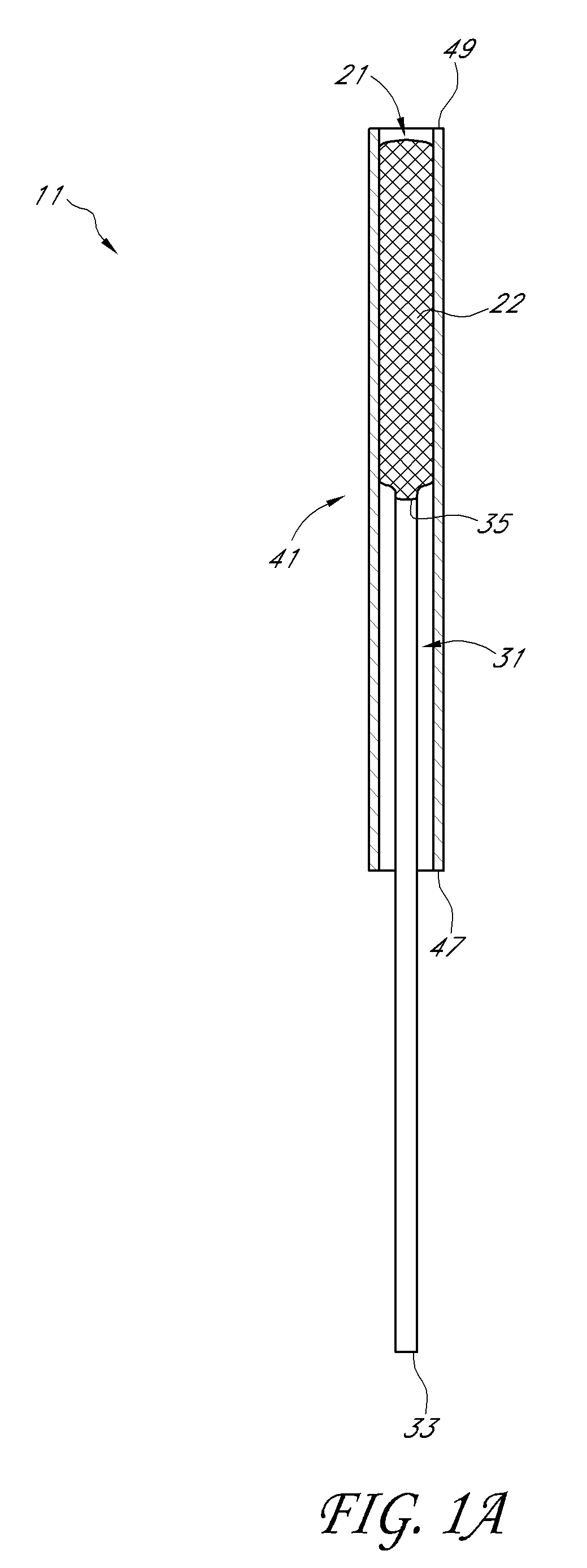
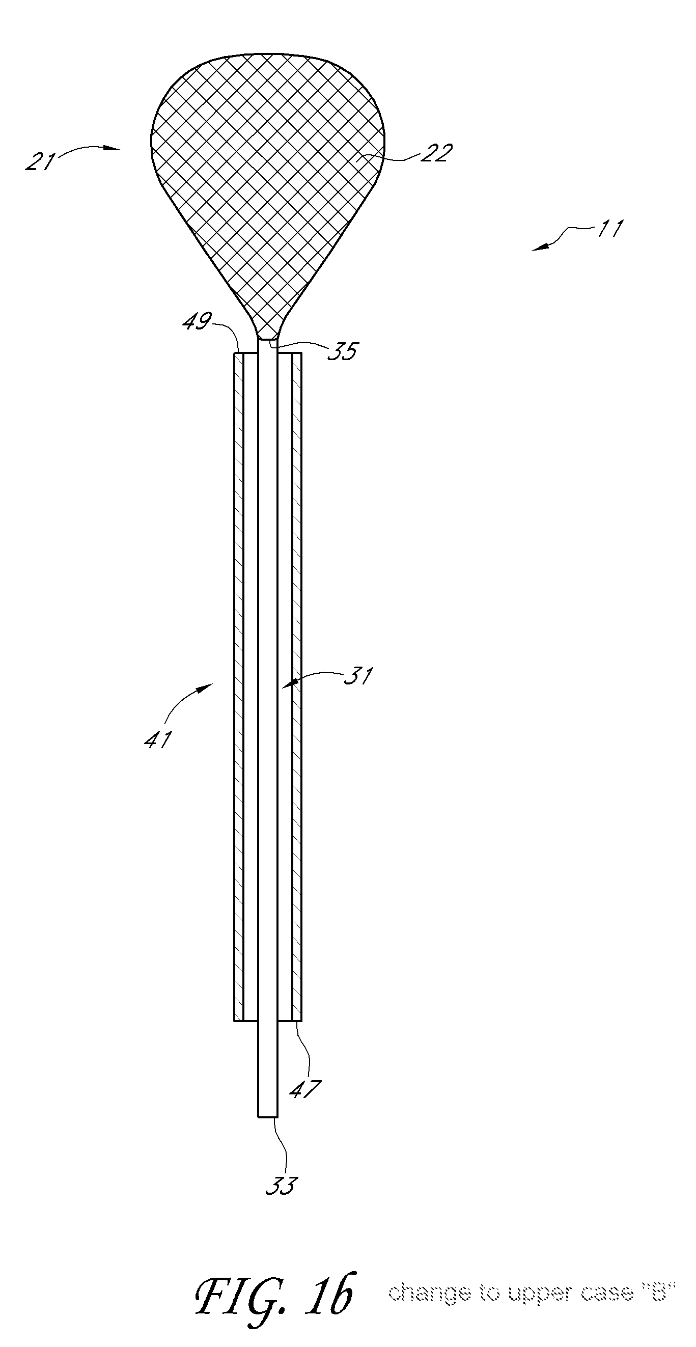
[0085]Referring now to FIGS. 1(a) and 1(b), there are shown top views, partly in section, of an embodiment of a device for distending a gynecological cavity, the device being constructed according to the teachings of the present invention and being represented generally by reference numeral 11. Additional features, methods and systems relating to the present invention are disclosed in U.S. patent application Ser. No. 11 / 923,357 filed Oct. 24, 2007, entitled Mechanical Distension Systems for Performing a Medical Procedure in a Remote Space, the disclosure of which is hereby incorporated in its entirety herein by reference.

[0086]Device 11, which is particularly well-suited for distending a uterus of a patient, comprises expandable means. In the present embodiment, said expandable means comprises a self-expanding basket 21. Basket 21 may be a resiliently-biased foldable weave of filaments 22 made of Nitinol (nickel-titanium alloy) shape-memory alloy, spring steel or a similar shape-mem...


PUM


Abstract

Method and device for distending a gynecological cavity. According to one embodiment, a mechanical, non-fluid device is used to distend the gynecological cavity. Such devices include, for example, self-expanding members, such as resilient baskets, coils, whisks, prongs, and loops, or mechanically expanded members, such as inflatable balloons, mechanically-expanded cages and loops, and scissor jacks. The device may serve a purpose in addition to distension, such as illumination, imaging, irrigation, drug delivery, resection and cauterization.

Description

CROSS-REFERENCE TO RELATED APPLICATIONS[0001]The present application claims the benefit under 35 U.S.C. 119(e) of U.S. Provisional Patent Application Ser. No. 60 / 910,625, filed Apr. 6, 2007, and U.S. Provisional Patent Application Ser. No. 60 / 910,618, filed Apr. 6, 2007, all of which are incorporated herein by reference.FIELD OF THE INVENTION[0002]The invention is in the general field of medical tools, and more specifically relates to tools and methods involving distending a gynecological cavity.DESCRIPTION OF THE RELATED ART[0003]The present invention relates generally to methods and devices for distending a gynecological cavity and relates more particularly to a new method and device for distending a gynecological cavity.[0004]It is desirable in many types of situations for medical personnel to perform diagnostic and / or therapeutic procedures within a gynecological cavity. For example, one may wish to detect and / or to treat conditions including, but not limited to, the presence of...

Claims


Application Information

Patent Timeline
IPC IPC(8): A61B17/42A61M29/02
CPCA61B1/303A61B17/0218A61B17/12013A61B17/12045A61B17/12099A61B17/12136A61B17/32002A61B17/320068A61B17/320783A61B17/42A61B2017/00084A61B2017/00278A61B2017/00557A61B2017/00862A61B2017/00876A61B2017/00893A61B2017/12018A61B2017/12127A61B2017/22038A61B2017/306A61B2019/464A61B2019/5206A61F6/20A61M25/0026A61M25/1002A61M25/1011A61M37/0092A61M2025/1047A61M2025/105A61B1/0615A61B1/0661A61M31/002A61M29/02A61M25/09A61F6/225A61B17/4241A61N7/022A61B17/22A61B5/6875A61N5/062A61N5/0603A61B17/30A61B2090/306A61B2090/064A61B2017/32007A61B2017/320071A61B17/02
Inventor GRUBER, WILLIAM H.ADAMS, RONALD D.LORENZ, MICHAEL A.CRISP, RYAN S.CLCENAS, CHRIS W.BURCHFIELD, BRENT L.DICESARE, PAULRADZIUNAS, JEFFREYVIGLIOTTI, DANIEL
Owner HOLOGIC INC
Learn More