Anastomosis systems and methods

a technology of anastomosis and system, applied in the field of anastomosis systems and methods, can solve the problems of increasing the chance of artery trauma, difficult to construct an arterial anastomosis, and almost a technical impossibility using minimally invasive techniques

Inactive Publication Date: 2008-10-09
MEDTRONIC INC
View PDF102 Cites 16 Cited by
  • Summary
  • Abstract
  • Description
  • Claims
  • Application Information

AI Technical Summary

Benefits of technology

[0015]Other aspects in accordance with principles of the present disclosure relate to a method of performing an anastomosis. The method includes providing a surgical connection apparatus including a plurality of delivery assemblies each defining a distal region and releasably retaining a self-closing clip. The distal regions are passed through a wall of a tubular graft structure adjacent a distal end thereof. The distal regions of the delivery assemblies are introduced into a hole formed in a second structure that otherwise defines an exterior surface opposite an interior surface. The plurality of self-closing clips are simultaneously deployed from the delivery assemblies such that the clips pass through the tubular graft structure and the second structure to secure...

Problems solved by technology

Constructing an arterial anastomosis is technically challenging for a surgeon in open surgical procedures, and is almost a technical impossibility using minimally invasive techniques.
One problem encountered in either CABG procedure approach is the need to perform the procedure while simultaneously maintaining sufficient function of the patient's circulatory system.
Among the drawbacks associated with aortic clamping is an increased chance of trauma to the arteries caused by ligatures at the clamped site, the possible dislodging of plaque within the clamped vessel wall.
Clamping the artery creates a risk of plaque being released into the blood stream that in turn has the potential of causing a stroke, occlusion of a smaller peripheral vessel, or other vascular trauma.
In a beating heart procedure, full clamping (i.e., cross-clamping) of the aorta for graft attachment at the proximal anastomosis is not feasible.
This type of clamping procedure poses the same risks described above with respect to cross-clamping (e.g., the risk of release of plaque and resultant cause of a stroke, occlusion of ...

Method used


Image

  • Anastomosis systems and methods
  • Anastomosis systems and methods
  • Anastomosis systems and methods

Examples


Embodiment Construction

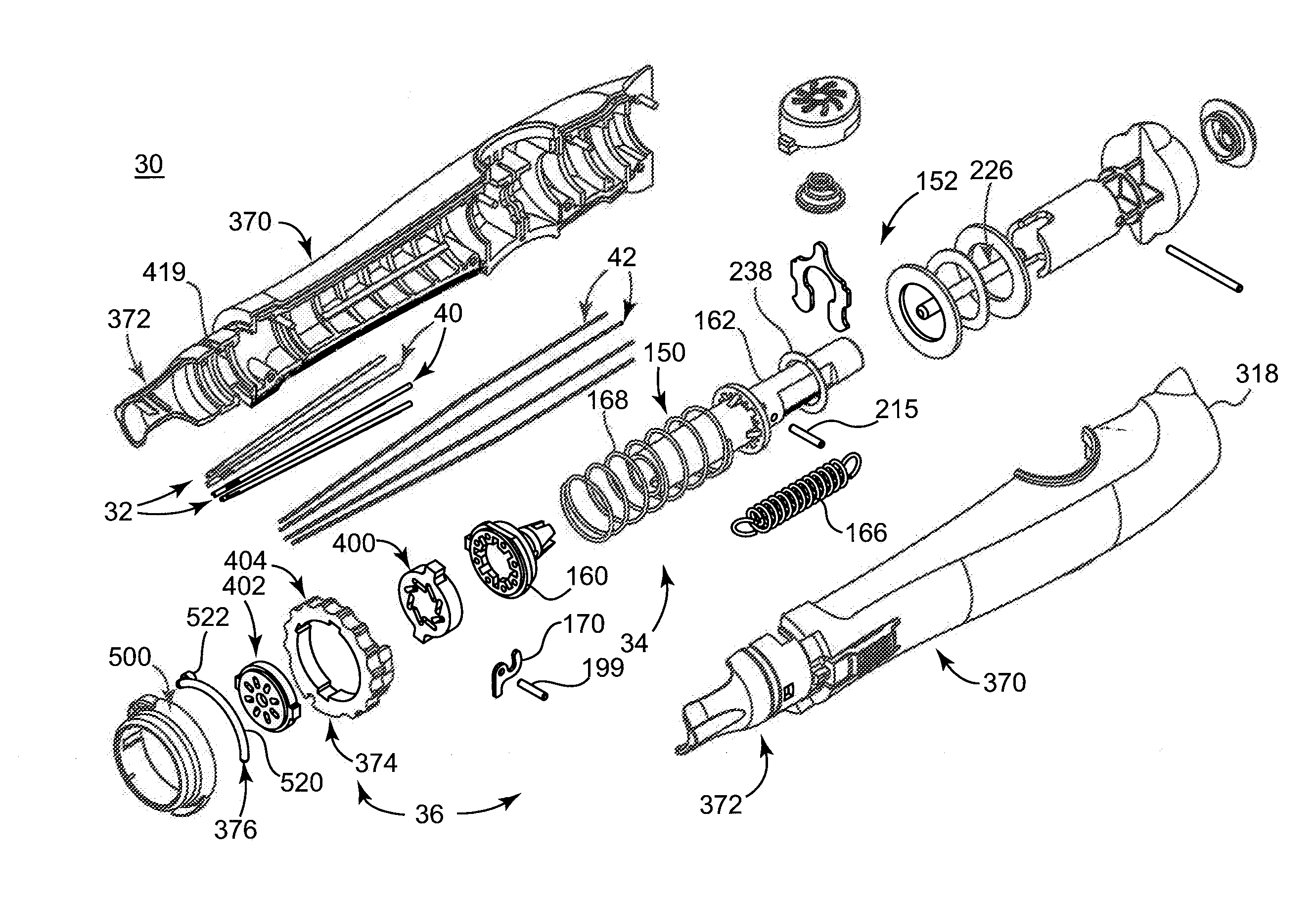
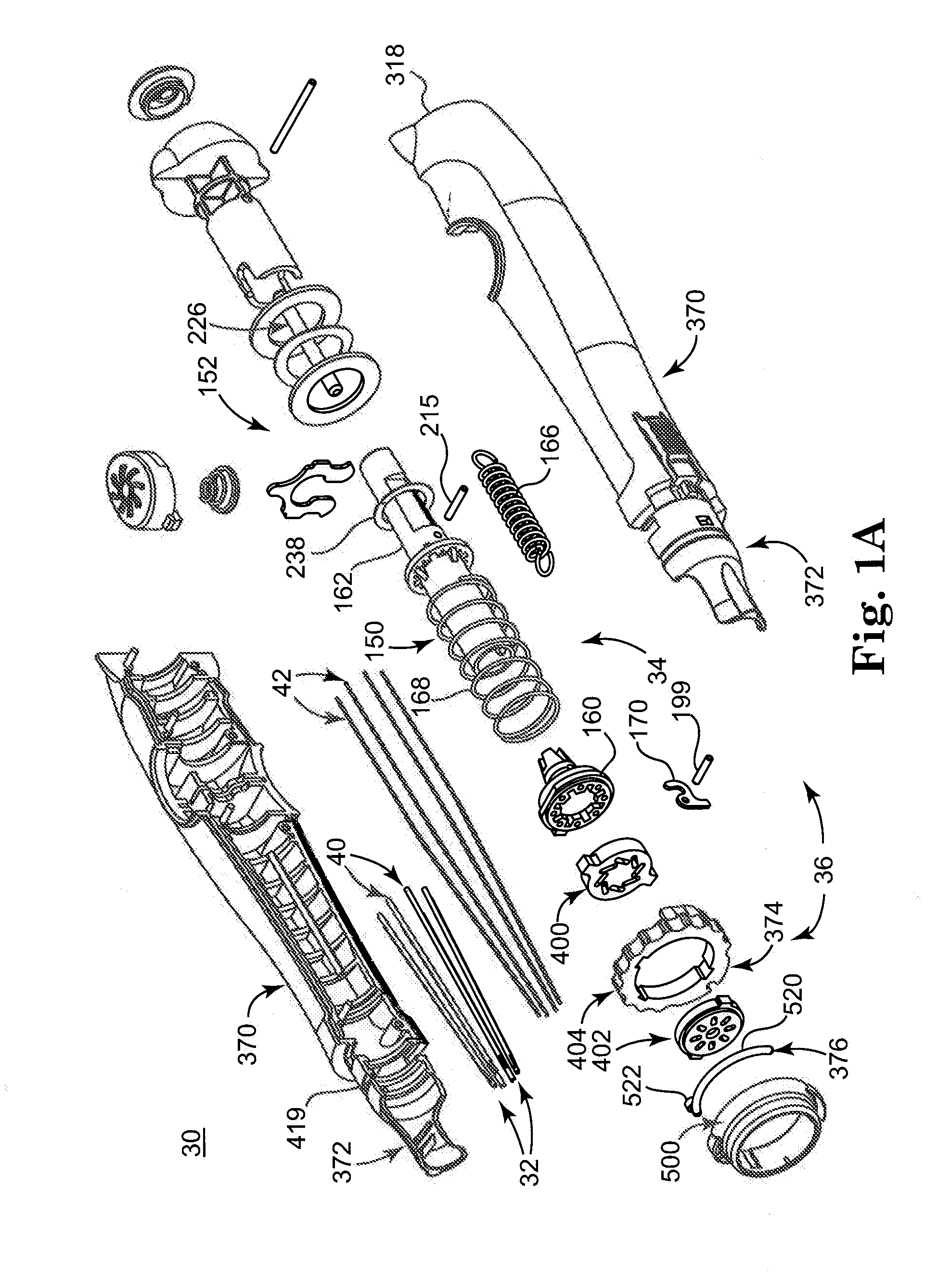
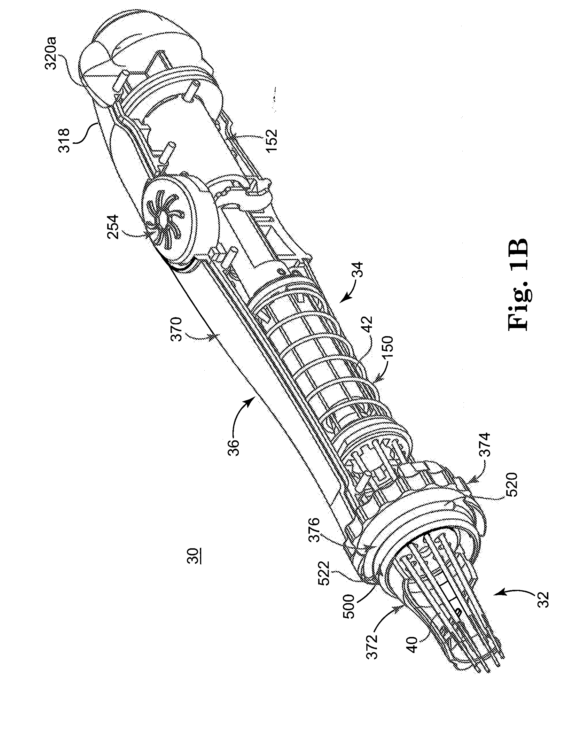
[0086]One configuration of a surgical connection apparatus 30 in accordance with aspects of the present disclosure is shown in FIGS. 1A and 1B. The apparatus 30 includes a plurality of delivery assemblies 32, a drive mechanism 34, and a housing assembly 36 (each referenced generally in FIGS. 1A and 1B). Details on the various components are provided below. In general terms, however, the housing assembly 36 maintains the delivery assemblies 32 and the drive mechanism 34. Each of the delivery assemblies 32 releasably maintains a self-closing clip (not shown). The drive mechanism 34, in turn, operates to effectuate substantially simultaneous release of each of the clips from corresponding ones of the delivery assemblies 32. With this construction, then, a tubular graft structure (not shown) can be mounted to the delivery assemblies 32 and subsequently secured to a second structure (not shown) via deployment of the clips in performing an anastomosis procedure.

[0087]The devices, systems,...


PUM


Abstract

A surgical connection apparatus including a plurality of delivery assemblies, a housing assembly, and a drive mechanism. The delivery assemblies each include an outer member, an inner member, and optionally a retention member. The inner member is disposed within the outer member, terminates at a distal tip and forms an internal passage that is open at a window. The delivery assemblies releasably retain a self-closing clip. The housing assembly maintains the delivery assemblies in a generally circular arrangement. The drive mechanism operates to transition the delivery assembly in releasing a self-closing clip from the corresponding delivery assembly. With this construction, a plurality of self-closing clips can be simultaneously deployed in a manner effectuating, for example, an end-to-side anastomosis.

Description

CROSS-REFERENCE TO RELATED APPLICATIONS[0001]This application claims priority under 35 U.S.C. §119(e)(1) to U.S. Provisional Patent Application Ser. No. 60 / 883,615, filed Jan. 5, 2007, entitled “Anastomosis Systems and Methods”, and bearing Attorney Docket No. M190.200.101 / P0023238.00; and the entire teachings of which are incorporated herein by reference.BACKGROUND[0002]The present disclosure relates to systems and methods for surgically joining structures. More particularly, the present disclosure can involve anastomosing a tubular graft structure to a second structure, for example in a proximal anastomosis.[0003]Arterial replacement or bypass grafting has been performed for many years using open surgical techniques and a variety of prosthetic grafts. These grafts can be manufactured as fabrics, or prepared as autografts (from the patient's own tissues) or heterografts (from the tissues of animals or a combination of tissues), semi-synthetic tissues and / or alloplastic materials. A...

Claims


Application Information

Patent Timeline
IPC IPC(8): A61B17/08
CPCA61B17/0644A61B17/115A61B17/1155A61B2017/00243A61B2017/00867A61B2017/0647A61B2017/1107A61B2017/1135
Inventor SANDSTROM, JEFFREY D.MEYER, ERIC A.JELICH, DAMIAN A.REETZ, ROBERT H.BRISCOE, RODERICK E.
Owner MEDTRONIC INC
Why Eureka
Try Eureka