
Frame Relay Device

a relay device and frame relay technology, applied in the field of frame relay devices, can solve the problems of difficult identification of the source of the attack or intrusion, inability to prevent spoofing, and difficulty in spoofing mac addresses

Inactive Publication Date: 2008-10-09
FUJITSU LTD
View PDF4 Cites 60 Cited by
  • Summary
  • Abstract
  • Description
  • Claims
  • Application Information

AI Technical Summary

Benefits of technology

[0015]According to the frame relay device of the present invention, based on a table for registering an entry in which a relay object contains a pair of a MAC address and an IP address, a process of judging whether or not the relay object is a relay object (a routing object) for the received frame. In the frame relay device of the present invention, a relay process (a routing process) is performed for a frame to be routed. The table is structured such that a pair of a MAC address and an IP address legitimately assigned to a terminal or a relay device is registered whereas a pair of unauthorized addresses including a spoofed MAC or IP address is not registered. Therefore, according to the present invention, of all the received frames, a frame such as a spoofed one, which is not allowed to be relayed, can be prevented from being relayed.
[0039]According to the present invention, the MAC address learning section registers the pair of the source MAC address and the receiving port number of the frame first received from the port as a valid pair in the table so as to relay the frame. Therefore, according to the present invention, a spoofed frame received after the registration of the valid pair in the table can be prevented from being relayed.

Problems solved by technology

Conventionally, there is a problem of so-called address spoofing, in which an IP (Internet Protocol) address assigned to each network connection device or a MAC (Media Access Control) address unique to the above-mentioned network connection device is masqueraded as an address of another connection device.
Although MAC address spoofing is difficult as compared with the IP address spoofing, it is possible to spoof a MAC address used by someone else.
If an attack from a network such as a DoS (Denial of Services) attack or an intrusion from a network is performed on various servers or terminals connected to the Internet after address spoofing, it is difficult to identify a source of the attack or the intrusion because the IP address or the MAC address differs from its proper address.
Therefore, spoofing cannot be prevented.
Therefore, there is a possibility that all the terminals accessing a server through the relay device cannot receive the service provided by the server.
However, in the case where an attack persists while a spoofed address is being repeatedly modified or the like, it is difficult to determine whether or not a transmitted frame is an attack frame.
In this case, since a network corresponding to a path leading to the firewall or the load distribution device causes congestion with a large amount of attack frames, there arises a problem in that the other frames are not transmitted.
In consideration of installation cost and work, however, it is difficult to install such devices in the vicinity of all the terminals.

Method used


Image

  • Frame Relay Device
  • Frame Relay Device
  • Frame Relay Device

Examples


first embodiment

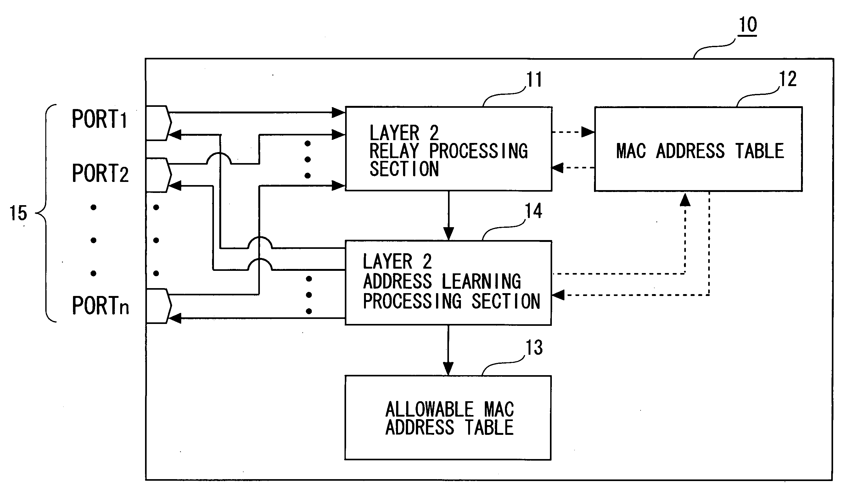
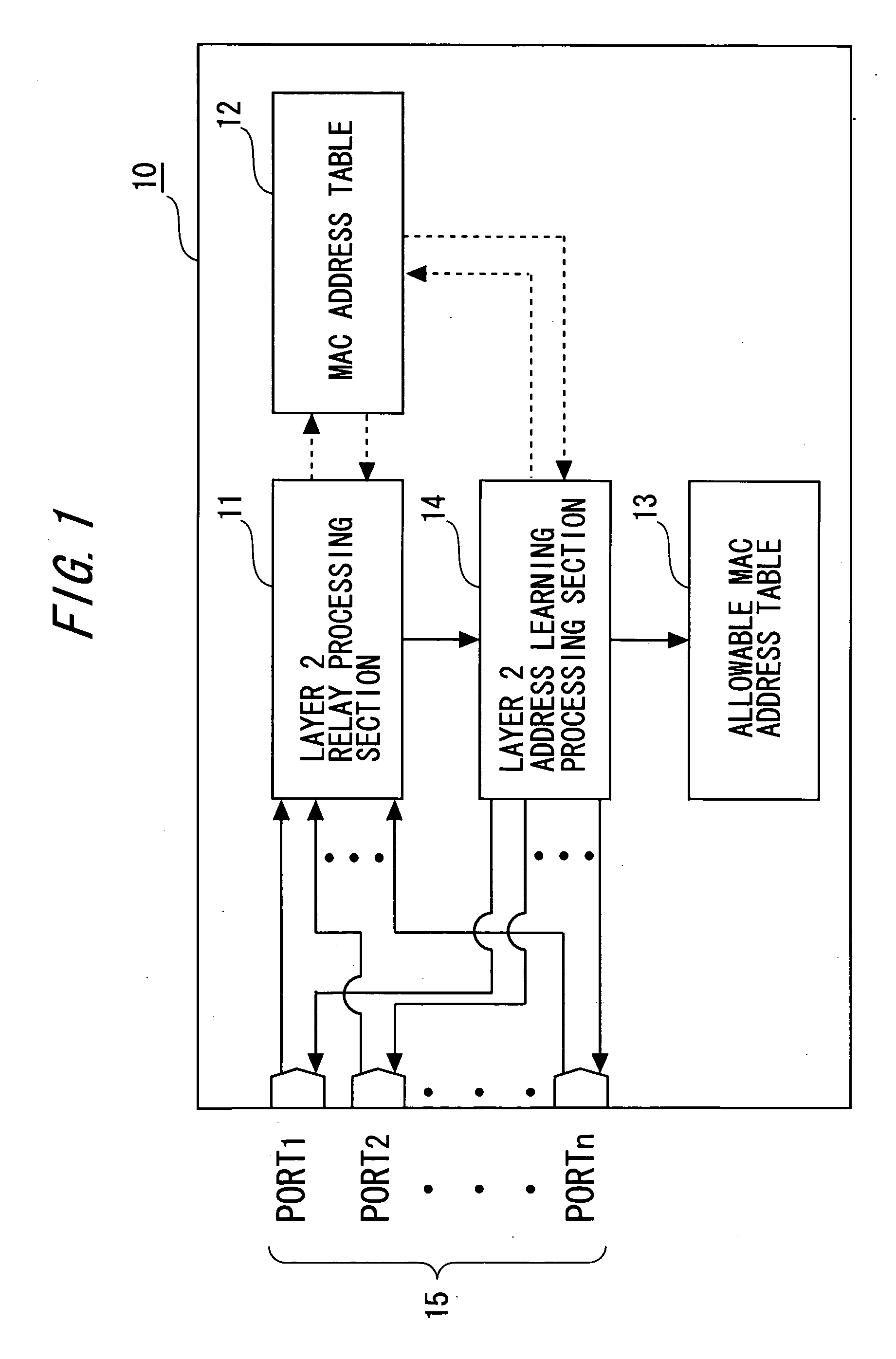
[0056]FIG. 1 is a block diagram showing a configuration of a frame relay device according to the first embodiment. A frame relay device 10 includes a layer 2 relay processing section 11, a MAC address table 12, a layer 2 address learning processing section 13, and an allowable MAC address table 14.

[0057]Note that, among the functional blocks of the frame relay device 10, the layer 2 relay processing section 11 functions as judging means and relay means of the present invention. The layer 2 address learning processing section 13 functions as judging means, registering means, and switching means of the present invention.

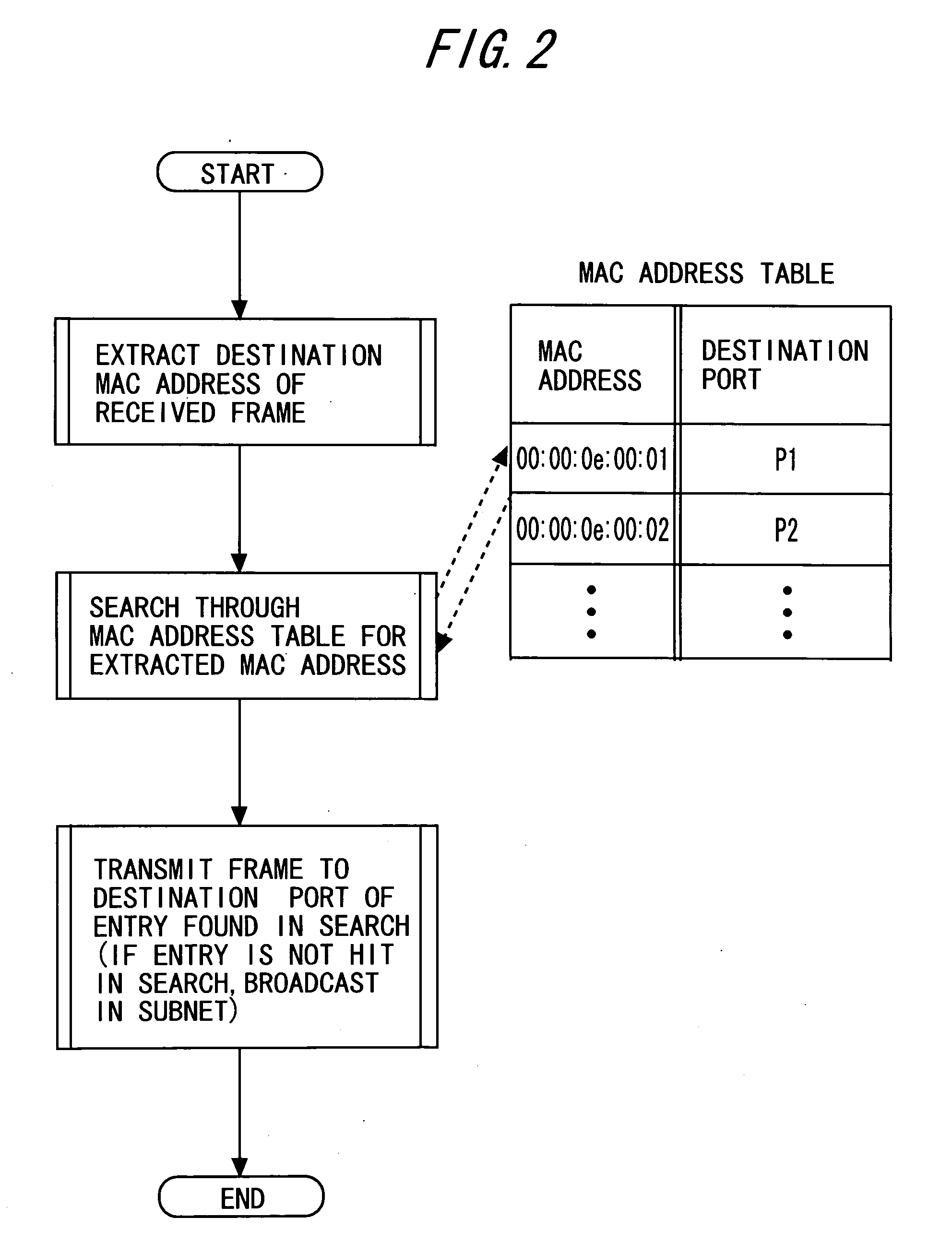
[0058]The layer 2 relay processing section 11 receives a frame received by each of a plurality of (for example, n) ports 15. The layer 2 relay processing section 11 refers to the MAC address table 12 so as to execute a layer 2 relay process described below for each frame. The layer 2 relay process determines a destination, to which a frame is relayed. After the layer 2...

second embodiment

[0097]Next, a second embodiment of the frame relay device of the present invention will be described.

[0098]FIG. 7 is a block diagram of a configuration of a frame relay device 20 according to the second embodiment. The frame relay device 20 includes the MAC address table 12, the allowable MAC address table 14, a layer 2 relay processing section 21 (corresponding to the layer 2 relay processing means of the present invention), a switch 22, a layer 2 address learning processing section 23, a relay object identifying section 24, ports 25, a routing processing section (corresponding to the layer 3 relay processing means of the present invention) 26, a routing object registration processing section 27, and a routing object check section 28.

[0099]The routing object registration processing section 27 functions as relay object registering means of the frame relay device of the present invention. In addition, the routing object check section 28 functions as judging means of the present inven...


PUM


Abstract

A frame relay device includes a table where an entry containing a combination of an MAC address and an IP address is registered to be used in the frame relay processing of a local device. Moreover, the frame relay device includes judgment means for searching the table by the transmission origin MAC address and the transmission origin IP address contained in the frame received and judging whether the combination of the transmission origin addresses is registered as a relay object in the layer 3. Furthermore, the frame relay device includes layer 3 relay processing means for performing layer 3 relay processing only for the frame which has been judged to contain the combination of the transmission origin addresses as a relay object.

Description

CROSS-REFERENCE TO RELATED APPLICATION[0001]This is a continuation of Application PCT / JP2003 / 012828, filed on Oct. 7, 2003, now pending, the contents of which are herein wholly incorporated by reference.TECHNICAL FIELD[0002]The present invention relates to a frame relay device, in particular, a frame relay device for preventing an attack to another server or terminal by address spoofing.RELATED ART[0003]Conventionally, there is a problem of so-called address spoofing, in which an IP (Internet Protocol) address assigned to each network connection device or a MAC (Media Access Control) address unique to the above-mentioned network connection device is masqueraded as an address of another connection device. Of such address spoofing, IP address spoofing can be easily practiced by, for example, rewriting a source IP address to appropriate someone else's address. Although MAC address spoofing is difficult as compared with the IP address spoofing, it is possible to spoof a MAC address used...

Claims


Application Information

Patent Timeline
Patent Type & Authority Applications(United States)
IPC IPC(8): H04L9/32G06F12/14H04L12/28H04L12/56
CPCH04L12/2854H04L45/742H04L49/25H04L49/602
Inventor NAMIHIRA, DAISUKE
Owner FUJITSU LTD
Learn More