Component Mounting Method and Apparatus

a technology for mounting components and mounting methods, which is applied in the direction of metal working apparatus, metal-working machine components, manufacturing tools, etc., can solve the problems of reducing mounting accuracy, reducing mounting accuracy, and high price of reference boards, and achieves high accuracy, high accuracy, and high accuracy.

Inactive Publication Date: 2008-10-16
PANASONIC CORP
View PDF5 Cites 31 Cited by
  • Summary
  • Abstract
  • Description
  • Claims
  • Application Information

AI Technical Summary

Benefits of technology

[0006]However, according to the method of carrying out the correction in each of the positions, it is possible that the position of the reference board is displaced by, for example, almost 1 mm between the first-time positioning and the second-time positioning of the reference board. Furthermore, the reference board is very expensive since the reference board is required to have very high accuracy, and its positioning is achieved by stopping the reference board in an approximate X-direction position without using a board stopper from the viewpoint of damage prevention. In addition, a board conveyor, which has a gap slightly smaller than 1 mm also in the Y-direction for conveyance, therefore has no reproducibility of the positioning of the reference board in the board holding section of the component mounting apparatus, and this becomes a factor that reduces the mounting accuracy.
[0007]As described above, the amounts of relative displacement between the individual positions of the robot are determined by positioning the reference board to an approximate position and thereafter recognizing the reference mark of the reference board, and the amounts of displacement are reflected in the placing position data of the mounting board during the mounting process. This therefore is a factor that reduces the mounting accuracy.

Problems solved by technology

Furthermore, the reference board is very expensive since the reference board is required to have very high accuracy, and its positioning is achieved by stopping the reference board in an approximate X-direction position without using a board stopper from the viewpoint of damage prevention.
In addition, a board conveyor, which has a gap slightly smaller than 1 mm also in the Y-direction for conveyance, therefore has no reproducibility of the positioning of the reference board in the board holding section of the component mounting apparatus, and this becomes a factor that reduces the mounting accuracy.
This therefore is a factor that reduces the mounting accuracy.
However, it is very difficult to accurately hold the reference board on the micrometer order in the board holding section as described above, and a special positioning device for accurately holding the board in the board holding section of the component mounting apparatus is necessitated.
Eventually, if the measured data is used directly as a correction value, it is impossible to accurately correct the X-Y robot unless the reference board is accurately positioned with high reproducibility.

Method used


Image

  • Component Mounting Method and Apparatus
  • Component Mounting Method and Apparatus
  • Component Mounting Method and Apparatus

Examples


first embodiment

[0114]Hereinbelow, a first embodiment according to the present invention will be described in detail with reference to the accompanying drawings.

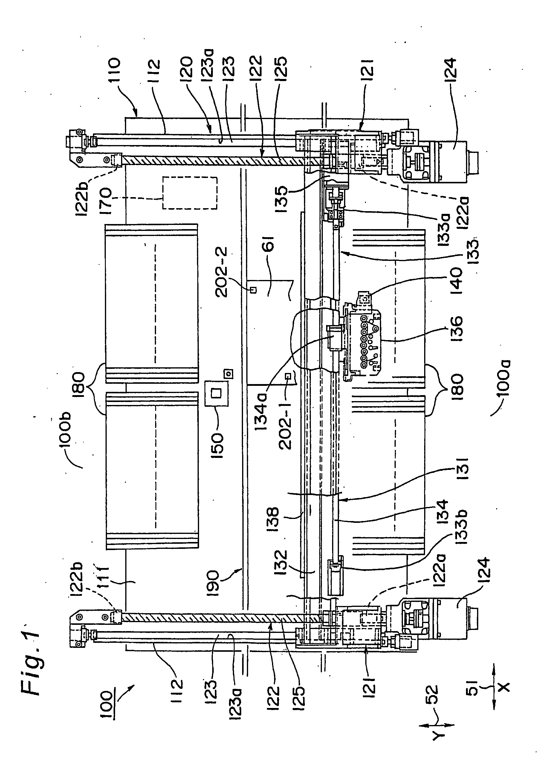
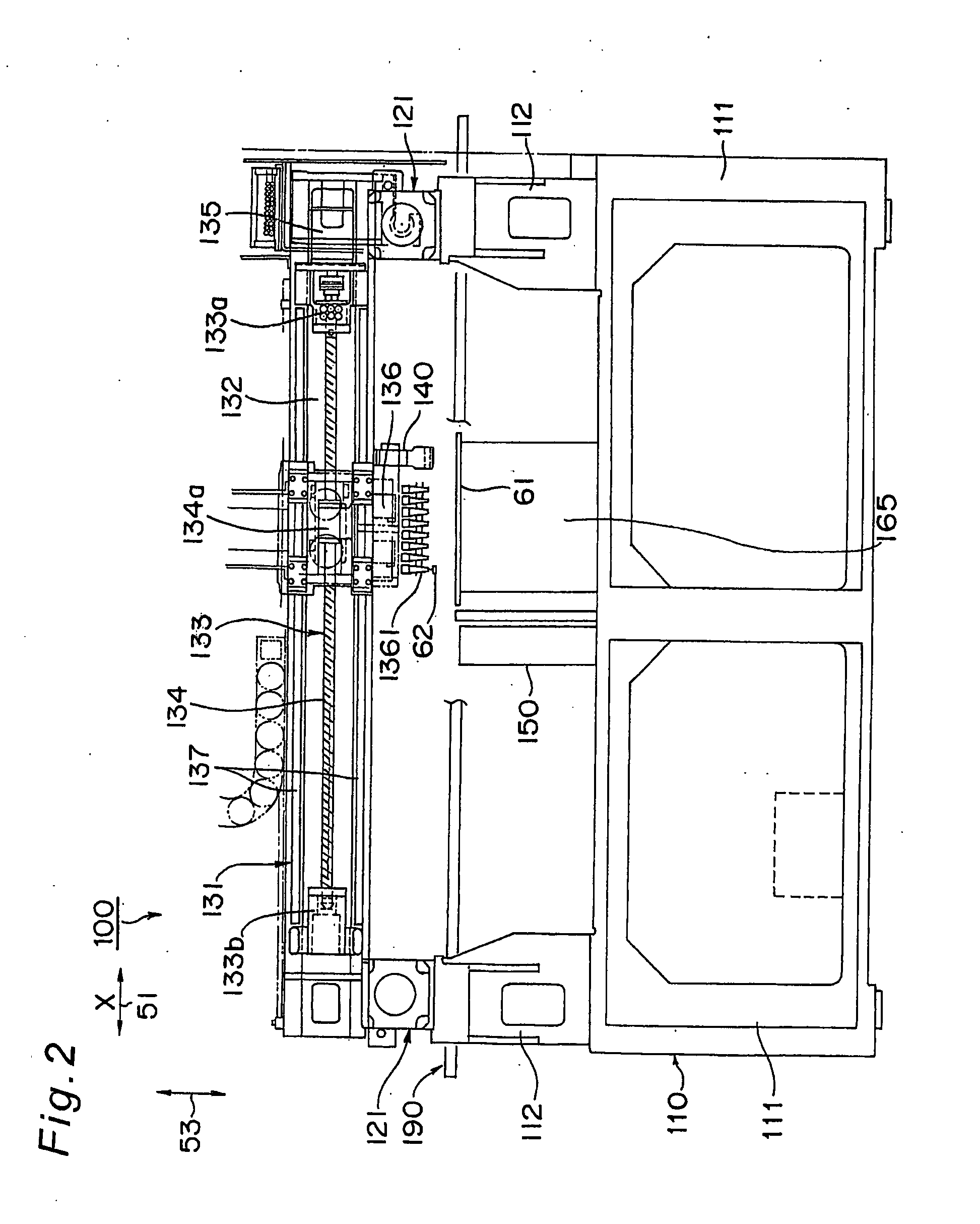
[0115]As shown in FIGS. 1 through 4, a component mounting apparatus 100 capable of carrying out the component mounting method according to the first embodiment includes a chassis 110, an X-Y robot 120, a board recognition camera 140 which is an example of a board recognition device for recognizing a recognition object on a board, a component recognition camera 150, a control unit 170, component feeding units 180, and a board conveyance unit 190, as the basic constituent elements.

[0116]The chassis 110 is a base on which the X-Y robot 120, the component recognition camera 150, the control unit 170, the component feeding unit 180, and the board conveyance unit 190 are installed, and is constructed of a rectangular parallelepiped base section 111 and Y-axis robot leg sections 112. The base section 111 and the Y-axis robot leg sections 112, i.e....

working examples

[0222]There are shown examples of a change in the amount of deviation and a change in the component placing accuracy between when the offset values of the areas according to the first embodiment are not effected and when the values are effected.

[0223]The offset values of the areas were measured by using the reference marks 201 of the board of a size of 428 mm×250 mm shown in FIG. 27.

[0224]In FIG. 27, when the reference marks 201 are recognized, the visual field center of the board recognition camera 140 is located in a position 60 mm apart from the center of the nozzle 1361 located at the right end in the X-direction (i.e., in the rightward direction in FIG. 27) in terms of the arrangement of the head 136. Therefore, in order to allow all the nozzles 1361 including the nozzle located at the left end and the nozzle located at the right end to be positioned in every region on the board 61, the board recognition camera 140 is required to be moved in the X-direction (i.e., in the rightw...

second embodiment

[0254]The present invention is not limited to the above-described embodiment and may be embodied in other various forms. A component mounting method and apparatus according to a second embodiment of the present invention will be described below.

[0255]In the component-placing-position correction method for component mounting described in the foregoing first embodiment, it is assumed that the posture of the component placing head 136 does not change during the move by the X-Y robot 120. More specifically, for example, in the case where the component placing head 136 supported by the X-axis robot 131 is moved from position A to position B along the X-axis direction as viewed in the figure by the X-axis robot 131 as shown in the schematic plan view of the component mounting apparatus 100 of FIG. 39, it is assumed that the component placing head 136 is moved while it is constantly held in its posture generally parallel to the X-axis frame 132 of the X-axis robot 131.

[0256]However, the X-...


PUM

PropertyMeasurementUnit
angleaaaaaaaaaa
sizeaaaaaaaaaa
sizeaaaaaaaaaa

Abstract

Reference marks arranged at specified intervals on a glass board are recognized, and from its recognition results, offset values for individual areas matching the board size are determined as numerical values for correction use, and further corresponding offset values for individual movement positions of a component placing head are reflected as numerical values for correction use in operation of placing position correction, mark recognition correction, or measurement of placing position offset values, respectively. Thus, high-accuracy placing is achieved. Moreover, correction of positional displacement of a component holding member due to an inclination of the component placing head is performed.

Description

TECHNICAL FIELD[0001]The present invention relates to a component mounting apparatus and method for placing components on a board with high accuracy.BACKGROUND ART[0002]Although component mounting process including suction of a component by the nozzle of a component suction head, recognition of the sucked component by the camera and its mounting onto the board has been carried out by moving the component suction head in the X- and Y-directions by driving an X-Y robot, it has not been able to achieve high mounting accuracy due to the distortion of the component mounting apparatus itself no matter how the component recognition accuracy has been improved. The distortion of the component mounting apparatus itself is attributed to poor machining accuracy or poor assembling accuracy of the X-Y robot of the component mounting apparatus.[0003]The impossibility of high-accuracy component placing onto the board during the placing process due to the distortion of the X-Y robot attributed to th...

Claims


Application Information

Patent Timeline
Patent Type & Authority Applications(United States)
IPC IPC(8): H05K3/30H05K13/04H05K13/08
CPCH05K13/0413H05K13/08Y10T29/53178Y10T29/49133Y10T29/53183Y10T29/53087Y10T29/53187H05K13/041H05K13/0812H05K13/089
Inventor OKUDA, OSAMUKAWASE, TAKEYUKIYOSHIDOMI, KAZUYUKI
Owner PANASONIC CORP
Why Eureka
Try Eureka