Light weight metal framing member

a metal framing member and light weight technology, applied in the direction of girders, building repairs, walls, etc., can solve the problems of wood warping and going out of shape, scarce lumber supply, and increased costs, so as to reduce shrinkage and twisting of the framing member

Inactive Publication Date: 2008-10-16
BAILEY METAL PROD
View PDF6 Cites 129 Cited by
  • Summary
  • Abstract
  • Description
  • Claims
  • Application Information

AI Technical Summary

Benefits of technology

[0006]The present invention provides for a lightweight metal framing member having a central web and two parallel spaced apart side walls extending upwardly from the sides of the web. The framing member has at least one longitudinally oriented rib extending the length of the web of the framing member to aid in reducing shrinkage and twisting of the framing member when non-symmetrical reinforcing structures which do not extend across the width of the framing member are formed in the framing member.

Problems solved by technology

The use of wood members has its shortcomings, the supply of lumber is getting scarce, and costs have increased during recent years.
In addition, wood can warp and go out of shape when it becomes wet as well as being susceptible to fire damage and attack by vermin of various kinds.
However, the use of sheet metal framing members has not gained widespread acceptance for various reasons.
For example, the cost of the materials utilized to form metal studs has been increasing and the price advantages of metal studs over wood studs is decreasing.
It is believed this is due to uneven shrinkage in the length of the member across its width caused by the localized shrinkage of the metal as a result of the formation of the reinforcing structures in only a portion of the width of the metal from which the metal framing member is formed.
While the twisting does not affect the structural integrity of the metal framing member, it does detract from the appearance of the stud and makes the storage and installation of the metal framing member more difficult.

Method used


Image

  • Light weight metal framing member
  • Light weight metal framing member
  • Light weight metal framing member

Examples


Embodiment Construction

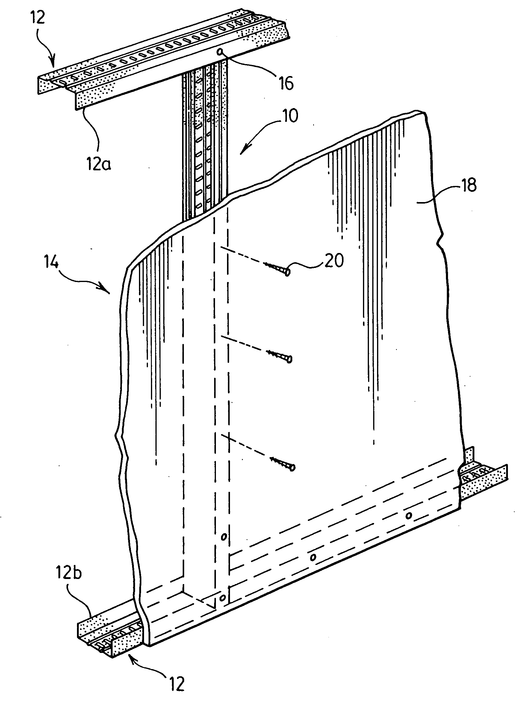
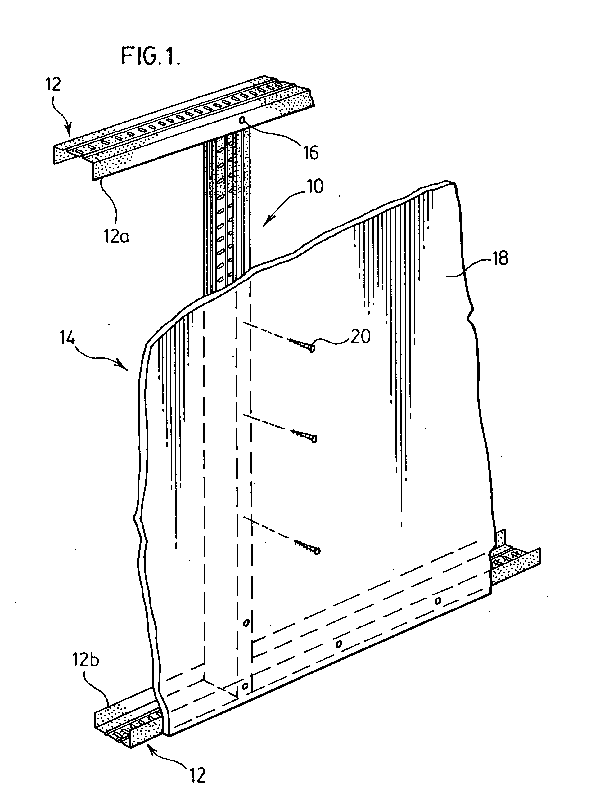
[0028]The present invention is directed to metal framing members such as metal studs 10 and tracks 12 utilized in framing partition walls 14 as illustrated in FIG. 1. The partition walls 14 are framed from a metal track 12 forming the top plates 12a and bottom plates 12b that are bridged by the parallel spaced apart metal studs 10. The spacing between the metal studs 10 is that typically utilized in construction of walls generally at 16 inches on center although other spacing such as 24 inches on center may be utilized. The studs 10 are attached to the top plate 12a and bottom plate 12b through the use of suitable screws 16. Once the partition wall 14 is framed utilizing the studs 10, top plate 12a and bottom plate 12b, a suitable wall covering material such as wall board 18 is attached to the partition wall utilizing suitable screws 20.

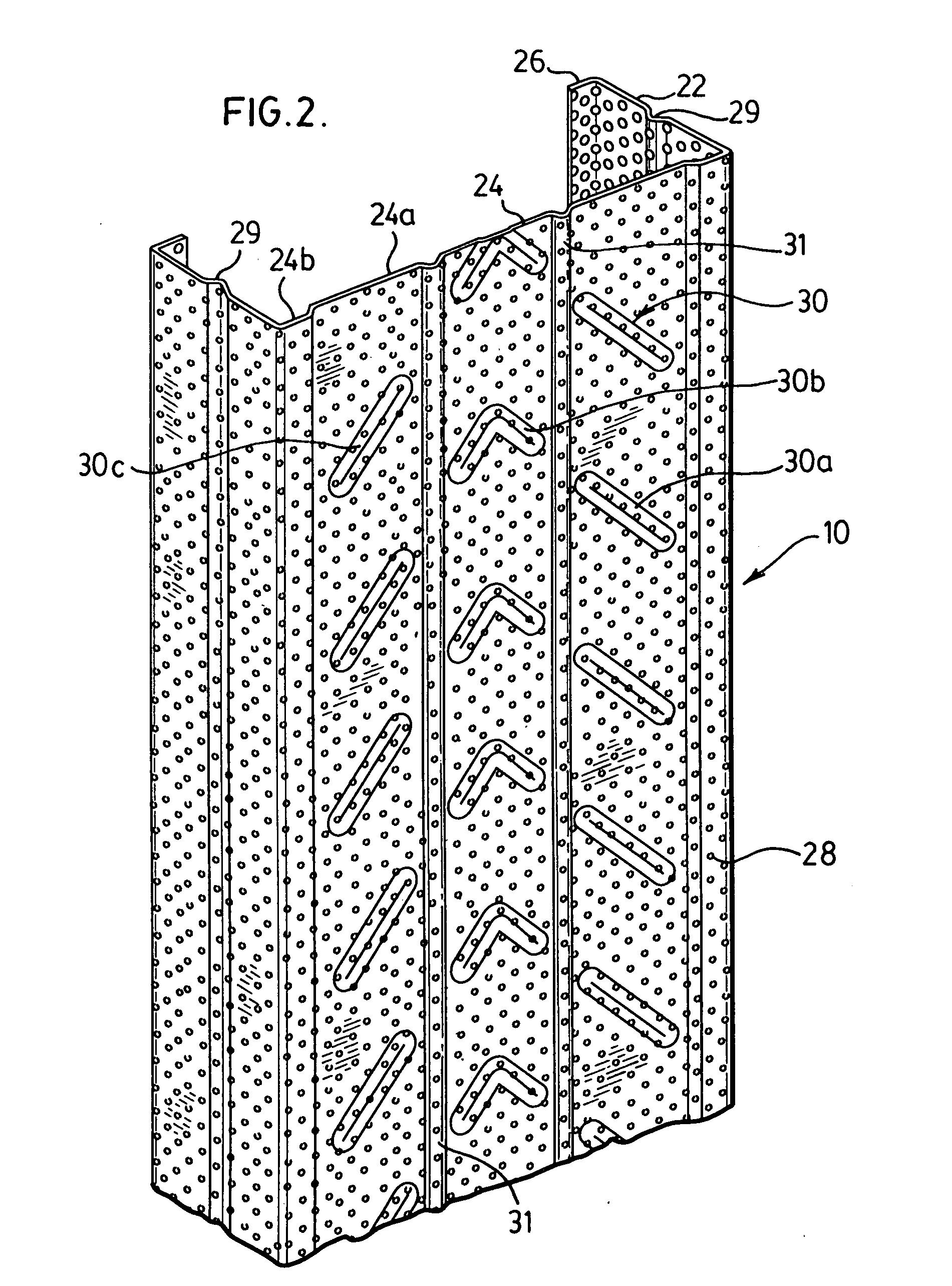
[0029]As illustrated in FIGS. 2, the metal stud 10 has a generally C-shaped rectangular cross-section with two parallel spaced apart side walls 22 a...


PUM


Abstract

The present invention provides for a lightweight metal framing member having a central web and two parallel spaced apart side walls extending upwardly from the sides of the web. The framing member has at least one longitudinally oriented rib extending the length of the web of the framing member to aid in reducing shrinkage and twisting of the framing member when non-symmetrical reinforcing structures are found in the framing member.

Description

FIELD OF THE INVENTION[0001]The present invention relates to metal framing members for use in constructing partition walls. In particular, the invention relates to metal studs and tracks for use in partition walls wherein the stud or track is provided with non-symmetrical patterns of structures to stiffen the material utilized in roll forming the metal stud or track and wherein the stud or track is also provided with longitudinally extending ribs to reduce or eliminate the tendency of the metal from which such stud or track is roll formed to shrink and twist.BACKGROUND OF THE INVENTION[0002]It is common practice in residential and many commercial buildings to separate the various rooms by partition walls to define the space of the room. Such partition walls are generally load bearing and have in the past been constructed of wood members including top and bottom plates and bridging studs. The use of wood members has its shortcomings, the supply of lumber is getting scarce, and costs ...

Claims


Application Information

Patent Timeline
Patent Type & Authority Applications(United States)
IPC IPC(8): E04B2/58
CPCE04B2/789E04C3/07E04C2003/0473
Inventor HOWCHIN, ROBERT
Owner BAILEY METAL PROD
Why Eureka
Try Eureka