Variable valve actuator with a pneumatic booster

a variable valve actuator and booster technology, applied in the field of actuators, can solve the problems of inability to meet the requirements of the conventional engine valve actuation system, the opening window of the cross-over valve has to be extremely narrow, etc., and achieves the effects of low seating velocity, large initial opening force, and substantial seating for

Inactive Publication Date: 2008-10-16
SKADERI GRUP LLC
View PDF8 Cites 47 Cited by
  • Summary
  • Abstract
  • Description
  • Claims
  • Application Information

AI Technical Summary

Benefits of technology

[0013]The present invention provides significant advantages over the prevailing fluid actuators and their control, especially those needed for the cross-over passage engine valve that needs a large initial opening force, a substantial seating force, a reasonably low seating velocity, a high actuation speed, and timing flexibility while consuming minimum energy by itself. The pneumatic booster is able to provide that large initial force, without adding too much construction complexity or demanding too much energy consumption or stretching the capacity and functional limits of the fluid or electromagnetic actuators, by tapping directly into the cross-over passage or the air storage tank. With the charge mechanis

Problems solved by technology

Also, the opening window of the cross-over valve has to be extremely narrow, especially at medium and high en

Method used


Image

  • Variable valve actuator with a pneumatic booster
  • Variable valve actuator with a pneumatic booster
  • Variable valve actuator with a pneumatic booster

Examples


Embodiment Construction

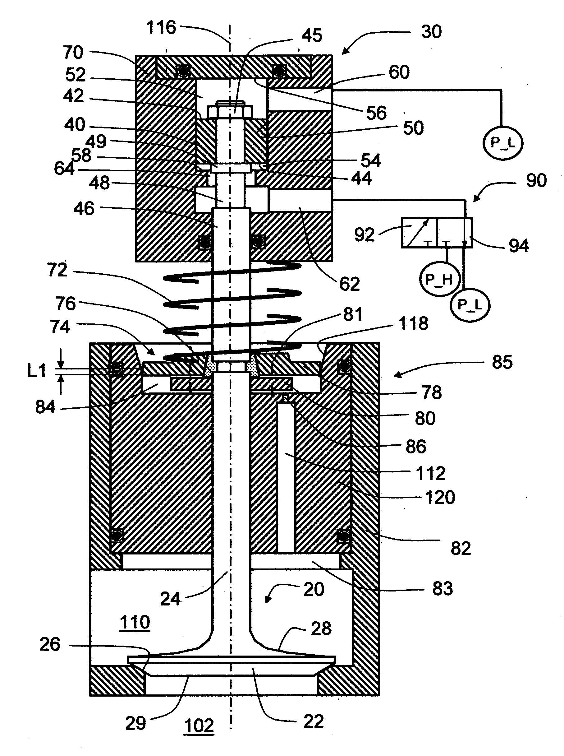
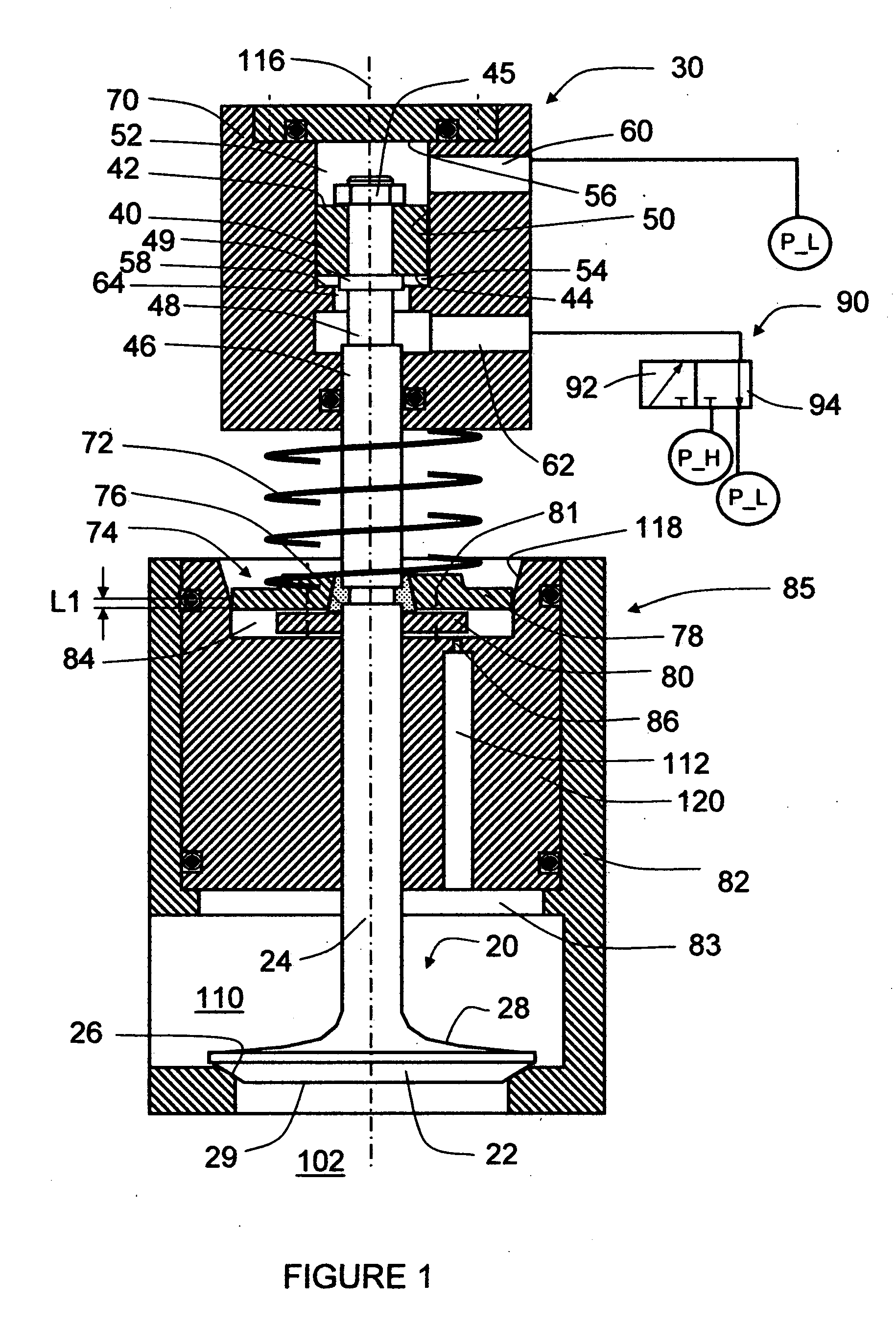
[0021]Referring now to FIG. 1, a preferred embodiment of the invention provides an actuator including a fluid driver 30, an actuation 3-way valve 90, an return spring 72, and a pneumatic booster 85. The load or control target of the actuator is an engine valve 20.

[0022]The actuation 3-way valve 90 supplies the fluid driver 30 through a second port 62 of the fluid driver 30. The 3-way valve 90 has two of its three ways connected with a low-pressure P_L fluid line and a high-pressure P_H fluid line, and the third way connected with the second port 62. A first port 60 of the fluid driver 30 is in fluid communication directly with the low-pressure P_L fluid line.

[0023]The actuation 3-way valve 90 is switched either to a left position 92 or a right position 94. At the left and right positions 92 and 94, the second port 62 is in fluid communication with the P_H and P_L lines, respectively.

[0024]The pressure P_H can be either constant or continuously variable. When variable, it is to accom...


PUM


Abstract

Actuators, and corresponding methods and systems for controlling such actuators, provide independent valve control with a large initial or opening force. In an exemplary embodiment, an actuator includes a driver further including a housing defining a longitudinal axis and first and second directions, an actuation mechanism capable of generating actuation force at least in the first direction, and a rod with one end operably connected with at least one part of the actuation mechanism and with the other end available for an operable connection with a load such as an engine valve; at least one return spring operably connected with the rod through a spring retainer assembly and biasing the rod in the second direction; and a pneumatic booster further including a pneumatic cylinder, a pneumatic piston operably connected with the rod through the spring retainer assembly and biasing the rod in the first direction, a charge mechanism providing a controlled fluid communication between the pneumatic cylinder and a high-pressure gas source, and a bleed mechanism providing a controlled fluid communication between the pneumatic cylinder to a low-pressure gas sink.

Description

FIELD OF THE INVENTION[0001]This invention relates generally to actuators and corresponding methods and systems for controlling such actuators, and in particular, to actuators offering efficient, fast, flexible control with large opening forces.BACKGROUND OF THE INVENTION[0002]A split four-stroke cycle internal combustion engine is described in U.S. Pat. No. 6,543,225. It includes at least one power piston and a corresponding first or power cylinder, and at least one compression piston and a corresponding second or compression cylinder. The power piston reciprocates through a power stroke and an exhaust stroke of a four-stroke cycle, while the compression piston reciprocates through an intake stroke and a compression stroke. A pressure chamber or cross-over passage interconnects the compression and power cylinders, with an inlet check valve providing substantially one-way gas flow from the compression cylinder to the cross-over passage, and an outlet or cross-over valve providing ga...

Claims


Application Information

Patent Timeline
IPC IPC(8): F01L9/02F01L9/10F01L9/16F01L9/18
CPCF01L9/02F01L9/026F01L2001/34446F01L2003/258F01L2009/028F01L2810/05Y10S137/906Y10T137/87096F01L9/18F01L9/16F01L9/10F01L13/00
Inventor LOU, ZHENG
Owner SKADERI GRUP LLC
Why Eureka
Try Eureka