Method of cementing an off bottom liner

a cementing method and bottom liner technology, applied in the direction of drilling casings, drilling pipes, borehole/well accessories, etc., can solve the problems of time-consuming and labor-intensive steps of drilling plugs out, unproductive cementing out the bottom of the liner, and leaving debris in the well

Inactive Publication Date: 2008-10-16
MAERSK OLIE & GAS AS
View PDF26 Cites 58 Cited by
  • Summary
  • Abstract
  • Description
  • Claims
  • Application Information

AI Technical Summary

Benefits of technology

[0009]One aspect of the current invention is therefore to provide a method of cementing an off bottom liner where it is not necessary to drill the plugs out at the end of the procedure in order to regain fluid communication to the wellbore below the liner.
[0015]In an advantageous form of a wiper plug, the wiper plug could comprise an outer wiper part and an inner hollow sleeve, and where the inner hollow sleeve is slideably arranged within the outer wiper part and is held in place by a release mechanism. In one embodiment, the inner hollow sleeve could be formed with through going openings which are exposed when the release mechanism releases and the inner hollow sleeve extends out the end of the wiper part. By arranging the through going openings in the hollow sleeve and exposing them when the sleeve slides forward, a large flow can be achieved through the plug. The openings can be formed as slots in the side of the sleeve which allow the openings to achieve a very large area, thereby reducing the flow resistance of the plug.
[0016]The wiper plug could further comprise a restraining mechanism which locks the inner hollow sleeve once it is extended into its extended position. In this way, the inner sleeve is prevented from closing once it has been opened. This is beneficial during the production of oil, since it would be detrimental to the well if the well was blocked accidentally.

Problems solved by technology

Therefore, pumping cement out the bottom of the liner would be unproductive.
However, one of the drawbacks of the method described above, is that the step of drilling the plugs out is time consuming.
Another drawback is that the drilling will leave debris in the well that could interfere with production equipment later in the well's life.

Method used


Image

  • Method of cementing an off bottom liner
  • Method of cementing an off bottom liner
  • Method of cementing an off bottom liner

Examples


second embodiment

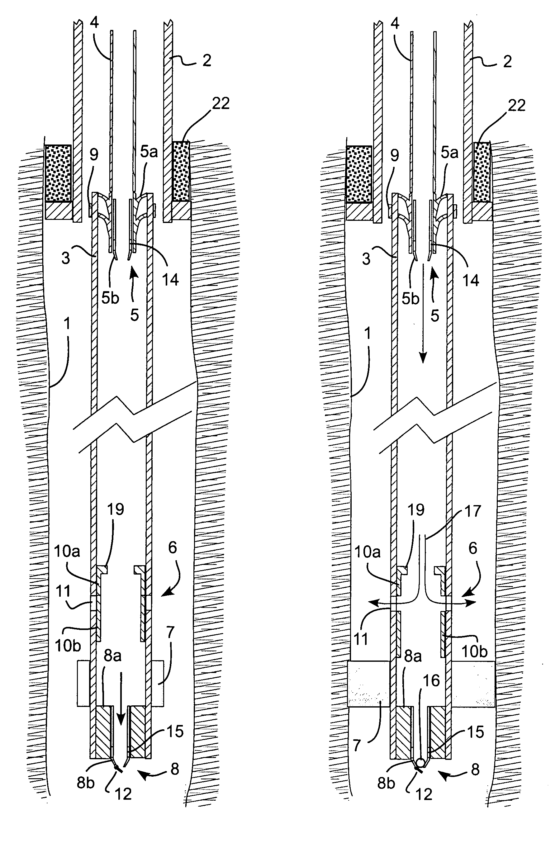
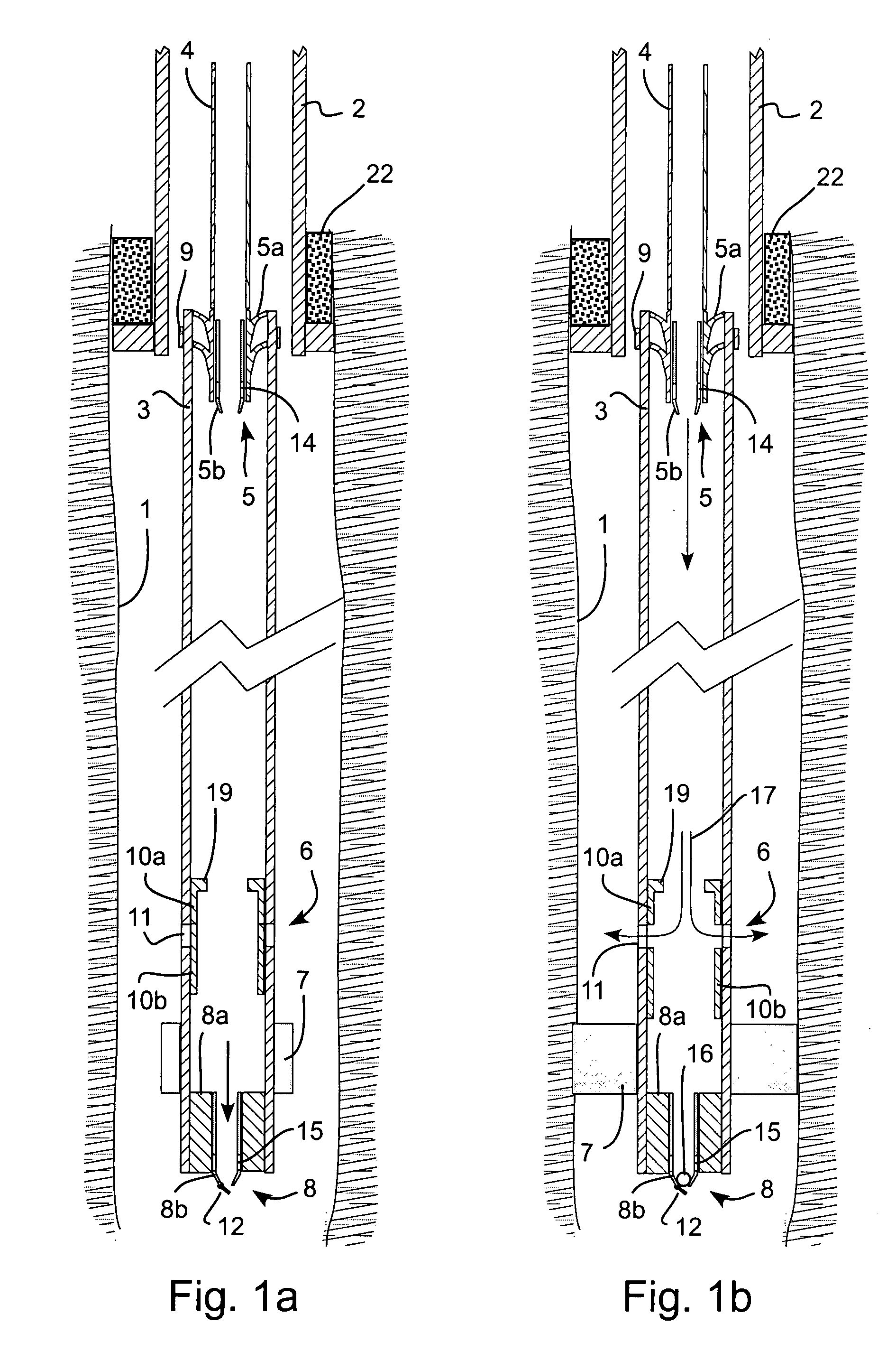
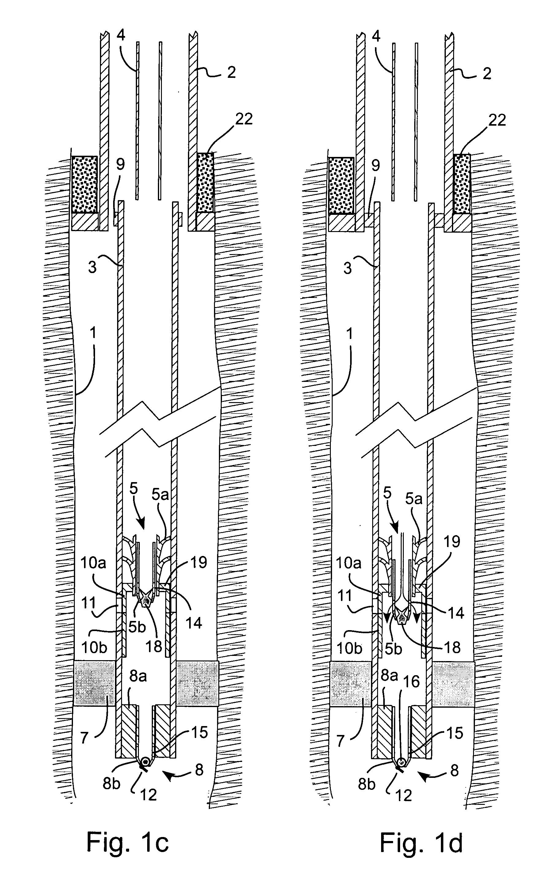
[0047]In the second embodiment, the bottom plug 30 is of the kind which is commonly called a “disappearing plug”. Plugs of this kind are well known in the industry and can, for example, comprise a plug 31 made of a hard packed material which dissolves when exposed to a high pressure. The plug 31 is arranged in an outer part 32. One example of such a plug is the “Mirage”™ plug manufactured by Halliburton.

[0048]The advantage of using a disappearing plug is that a simpler system is achieved. However, the disadvantage of using a disappearing plug is that during the running in of the liner 3, the bottom of the liner 3 is blocked and it is not possible to flush fluid out of the end of the liner 3. Not being able to flush out the end of the liner 3 is acceptable in cases where the well parameters are well known and there is little risk in the liner 3 installation. Therefore the solution with the disappearing plug is not always suitable.

first embodiment

[0049]The rest of the procedure is the same as the first embodiment, the only difference being that no ball is necessary to block the bottom plug 30. When it is desired to open the bottom plug 30, the pressure inside the liner 3 is raised above the predefined pressure point of the disappearing plug 30 and the plug 30 opens.

[0050]It should be mentioned, that instead of using a disappearing plug 30, a mechanical plug which is similar to the bottom plug 8 of the first embodiment can be used but which is already blocked at the start of the procedure. In this way, it is not necessary to drop a ball 16 into the well. However, as with the disappearing plug, it is not possible to flush fluid out of the end of the liner 3 during the running of the liner 3 when the liner 3 is equipped with this type of bottom plug.

third embodiment

[0051]FIGS. 3a-3f show some steps of a process for cementing an off-bottom liner. Most of the steps are the same as the previous methods, and the same elements have been given the same reference numerals.

[0052]In this embodiment, the difference is that two wiper plugs 5, 40 are suspended from the end of the liner hanger running tool 4. The two plugs are a top wiper plug 5 which is identical to the one used in the first and second embodiments and a bottom wiper plug 40 which is similar to the top wiper plug 5. The bottom wiper plug 40 is attached to the top wiper plug 5 with a release mechanism such as shear pins (not shown). The wiper plugs are of the kind which permit fluid flow through them until they are blocked by a plug 18, 41 which is pumped down the well or dropped into the well. These types of plugs 7, 8 are known in the industry and need not be described in more detail. The plugs which block the wiper plugs are typically in the form of a ball or a wiper dart. In the current...


PUM


Abstract

A method of cementing an off bottom liner including the steps of establishing a first flow blockage in the liner at a location down-hole of a cementing valve located in the side wall of the liner, opening the cementing valve which exposes openings in the sidewall of the liner, pumping cement down the liner and out through the openings in the sidewall of the liner, establishing a second flow blockage up-hole of the cementing valve, closing the cementing valve, opening the second flow blockage to establish fluid communication through the second flow blockage, and opening the first flow blockage to establish fluid communication through the first flow blockage. The steps of opening the first and second flow blockages are achieved by increasing the pressure in the liner above the blockages. In this way, it is possible to cement an off bottom liner and regain fluid communication to the wellbore below the liner without the need for any drilling operations.

Description

FIELD OF THE INVENTION[0001]The current invention relates to a method for cementing an off bottom liner comprising the steps of establishing a first flow blockage in the liner at a location down-hole of a cementing valve located in the side wall of the liner, opening the cementing valve which exposes openings in the sidewall of the liner, pumping cement down the liner and out through the openings in the sidewall of the liner, establishing a second flow blockage up-hole of the openings in the cementing valve, closing the cementing valve, opening the second flow blockage to establish fluid communication through the second flow blockage, and opening the first flow blockage to establish fluid communication through the first flow blockage. Off bottom liners are used in wellbores where the end of the liner does not reach the end of the wellbore. Off bottom liners can also be used in wellbores which are not purely vertical. Some wellbores can even be arranged horizontally.BACKGROUND[0002]D...

Claims


Application Information

Patent Timeline
Patent Type & Authority Applications(United States)
IPC IPC(8): E21B33/13E21B33/16
CPCE21B33/16E21B33/165
Inventor LUMBYE, PETER
Owner MAERSK OLIE & GAS AS
Why Eureka
Try Eureka