Mounting System For An Internal Bicycle Transmission

Inactive Publication Date: 2008-10-16
SRAM CORPORATION
View PDF7 Cites 15 Cited by
  • Summary
  • Abstract
  • Description
  • Claims
  • Application Information

AI Technical Summary

Benefits of technology

[0006]The control system may be mounted coaxially about the shell axis. The control system includes at least one sun pawl, a collar and a shift actuator. The collar provides a seat for the sun pawl. The sun pawl is configured to be selectively positionable between an engaged position nonrotatably connecting the sun gear to the collar, and a disengaged position allowing the sun gear to rotate relative to the collar. The shift actuator selectively positions the sun pawl between the engaged and disengaged positions. When the sun pawl is in the engaged position, rotation of the input crank assembly drives the planet gears to rotate about the planet shafts, the rotating planet gears overdriving the ring gear in a first transmission path. When the sun pawl is in the disengaged position, the rotation of the input crank assembly drives the rota

Problems solved by technology

This reactive torque may be substantial.
However, a disadvantage of a smaller chainring is the increased likelihood of chain derailment because there are fewer teeth engaging the chain.
One disadvantage of these configurations is that additional elements are mounted to the bottom bra

Method used


Image

  • Mounting System For An Internal Bicycle Transmission
  • Mounting System For An Internal Bicycle Transmission
  • Mounting System For An Internal Bicycle Transmission

Examples


Embodiment Construction

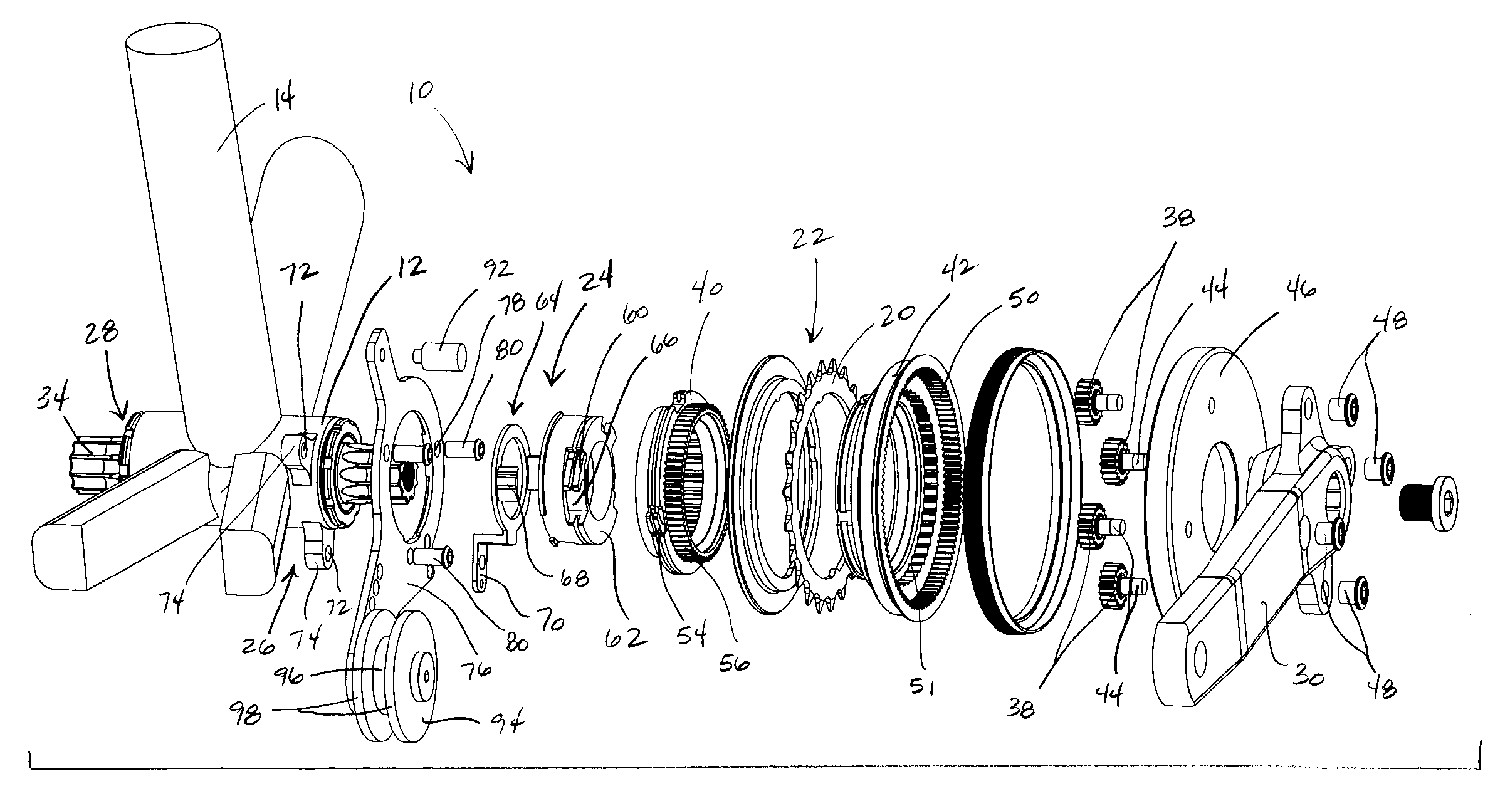
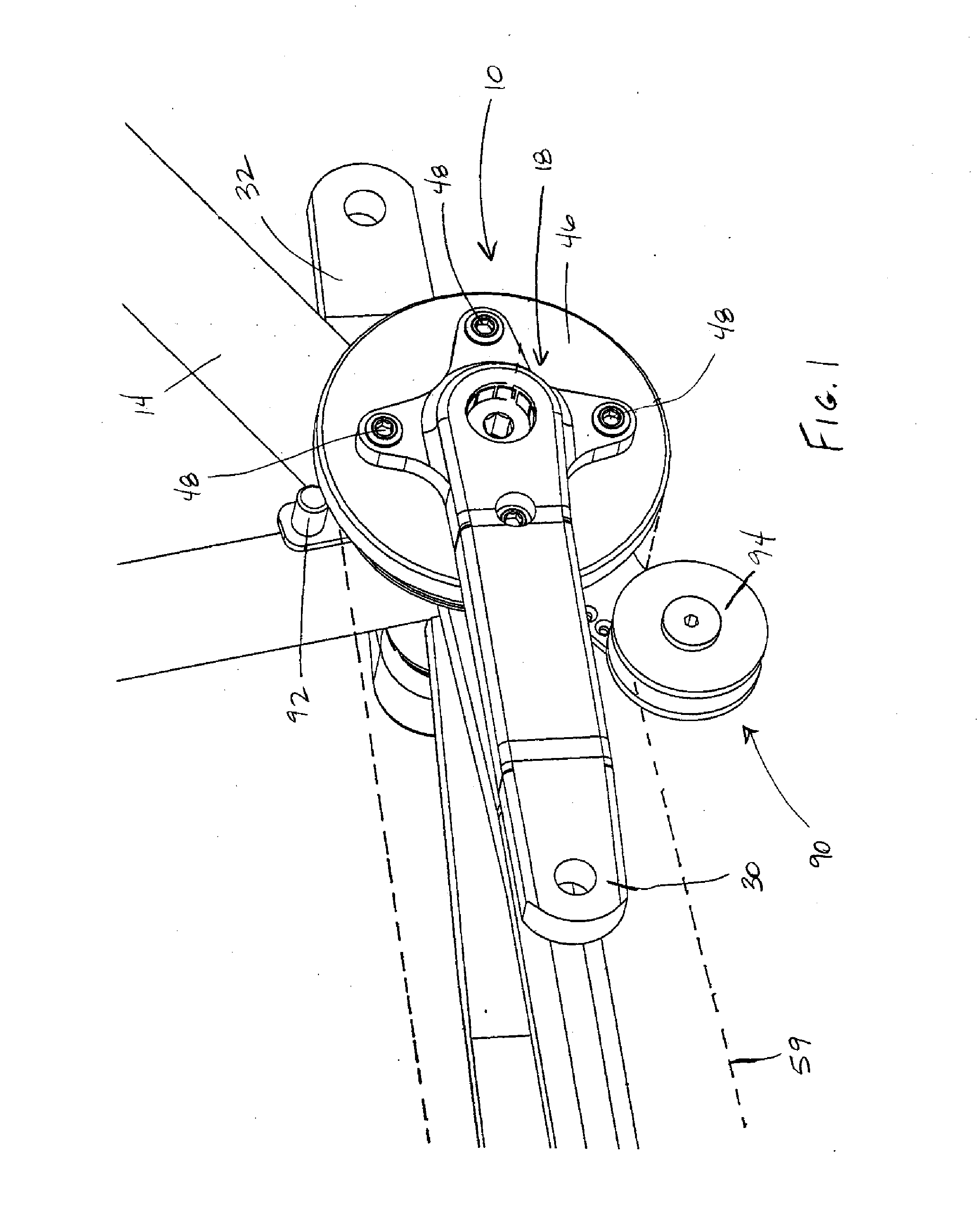
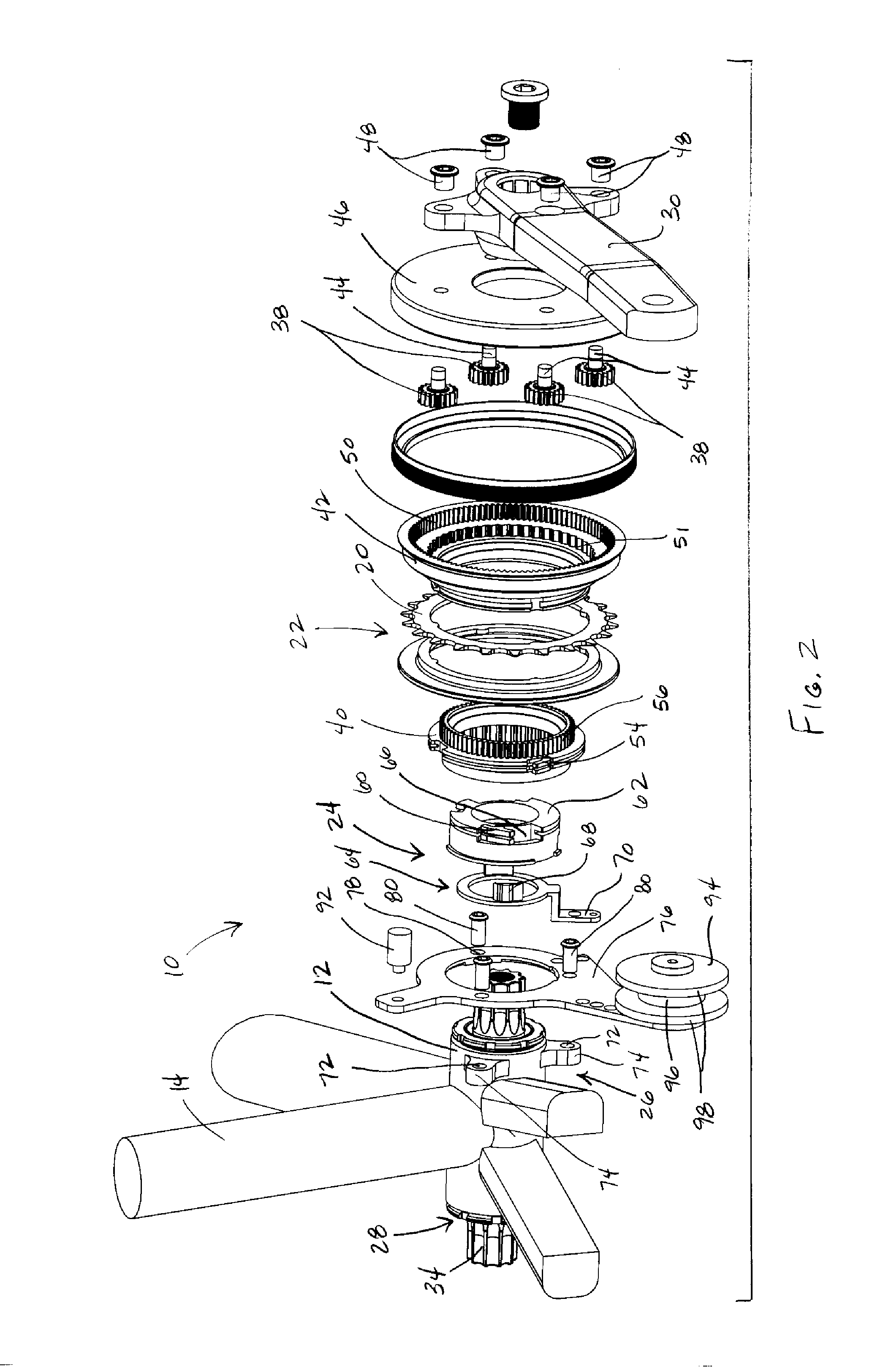
[0017]FIGS. 1-9 illustrate a bicycle transmission assembly 10 according to one embodiment of the present invention. Looking to FIGS. 1-4, the bicycle transmission assembly 10 is externally mounted to a bottom bracket shell 12 of a bicycle frame 14. The bottom bracket shell 12 has an axis 16 and connects various tubes of the bicycle frame 14. The bicycle transmission assembly 10 generally includes an input crank assembly 18, an output chainring 20, a planetary gear mechanism 22, a control system 24 and a mounting system 26. The crank assembly 18 is rotatably mounted to the bottom bracket shell 12. The crank assembly 18 includes a bottom bracket 28 that extends through the bottom bracket shell 12, with first and second crank arms 30, 32 rotatably connected to a crank axle 34. The bottom bracket 28 includes the crank axle 34 and bearings 36.

[0018]The planetary gear mechanism 22 is mounted coaxialty about the shell axis 16 and disposed inboard of the first crank arm 30. The planetary ge...


PUM


Abstract

A bicycle transmission assembly that is mountable to a bottom bracket shell of a bicycle frame. The bicycle transmission assembly includes an input crank assembly, an output chainring, a planetary gear mechanism, a control system and a mounting system. The planetary gear mechanism is mounted coaxially about an axis of the bottom bracket shell and provides a plurality of transmission paths. The control system is operatively connected to the planetary gear mechanism for selecting one of the transmission paths. The mounting system mounts the planetary gear mechanism and the control system to the bottom bracket shell. The mounting system includes at least one attachment point disposed on at least one frame boss extending radially outwardly from the bottom bracket shell. The control system is mounted nonrotatably to the at least one attachment point.

Description

BACKGROUND OF THE INVENTION[0001]The present invention relates to internal bicycle transmissions and more particularly to a mounting system for mounting an internal bicycle transmission to a bottom bracket shell.[0002]Internal bicycle transmissions may be located at the rear wheel hub and / or at the front crank assembly. Internal bicycle transmissions provide multiple transmission paths corresponding to multiple bicycle gear ratios. Typically, an internal bicycle transmission includes a planetary gear mechanism with a sun gear, a ring gear, a plurality of planet gears meshing with the ring gear, and sun gear and a carrier for supporting the planet gears. To shift between the multiple transmission paths, select elements of the planetary gear mechanism may be locked or unlocked. For example, when the sun gear is locked and the planet gears are driven, the ring gear is overdriven. This is referred to as overdrive, where the output at the ring gear rotates faster than the input at the cr...

Claims


Application Information

Patent Timeline
IPC IPC(8): B62M1/02B62M1/36
CPCB62K19/34Y10T74/20462B62M11/145B62M9/16
Inventor WESLING, KEVINSHIPMAN, CHRISTOPHERJORDAN, BRIAN
Owner SRAM CORPORATION
Why Eureka
Try Eureka