Rotor Core For Rotating Electrical Machine and Method of Manufacturing the Same

Inactive Publication Date: 2008-10-16
TOSHIBA LIFESTYLE PROD & SERVICES CORP +1
View PDF8 Cites 16 Cited by
  • Summary
  • Abstract
  • Description
  • Claims
  • Application Information

AI Technical Summary

Benefits of technology

[0010]According to the present invention, the blanks are blanked with the projection of the magnetic pole portion being embraced from longitudinal and lateral directions by the blanking blade. Thus, the yoke and the magnetic pole portion are accurately positio

Problems solved by technology

However, shaping Nd magnets and the like into a circumferential shape is disadvantageous in terms of manufacturing costs.
As described above, since the Nd magnets and t

Method used


Image

  • Rotor Core For Rotating Electrical Machine and Method of Manufacturing the Same
  • Rotor Core For Rotating Electrical Machine and Method of Manufacturing the Same
  • Rotor Core For Rotating Electrical Machine and Method of Manufacturing the Same

Examples


Example

[0023]A first embodiment applying the present invention to a permanent magnet electric motor of an outer rotor type will be described with reference to FIGS. 1 to 8.

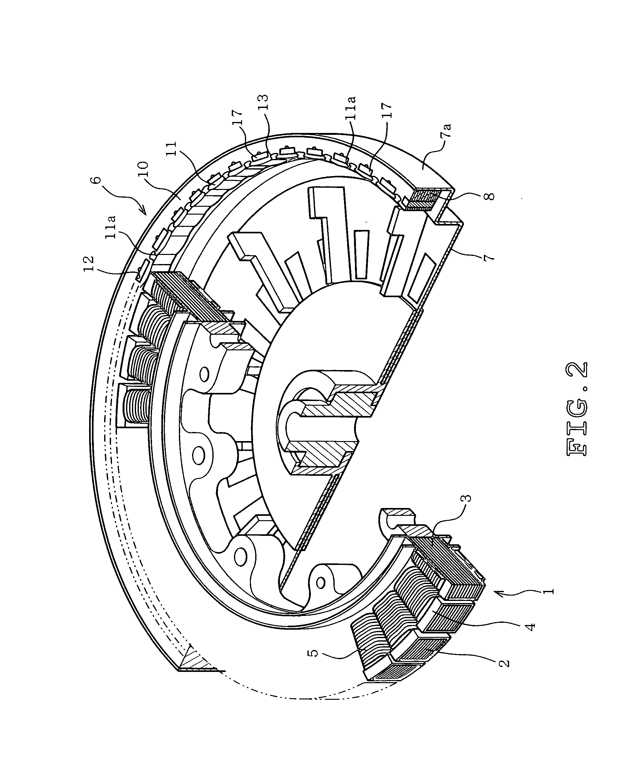
[0024]FIG. 2 illustrates a perspective view of a partially broken electric motor. In FIG. 2, a stator 1 includes a stator core 3 having multiple radial teeth 2, a resin 4 molded so as to cover the stator core 3, and a stator winding 5 wound on each tooth 2.

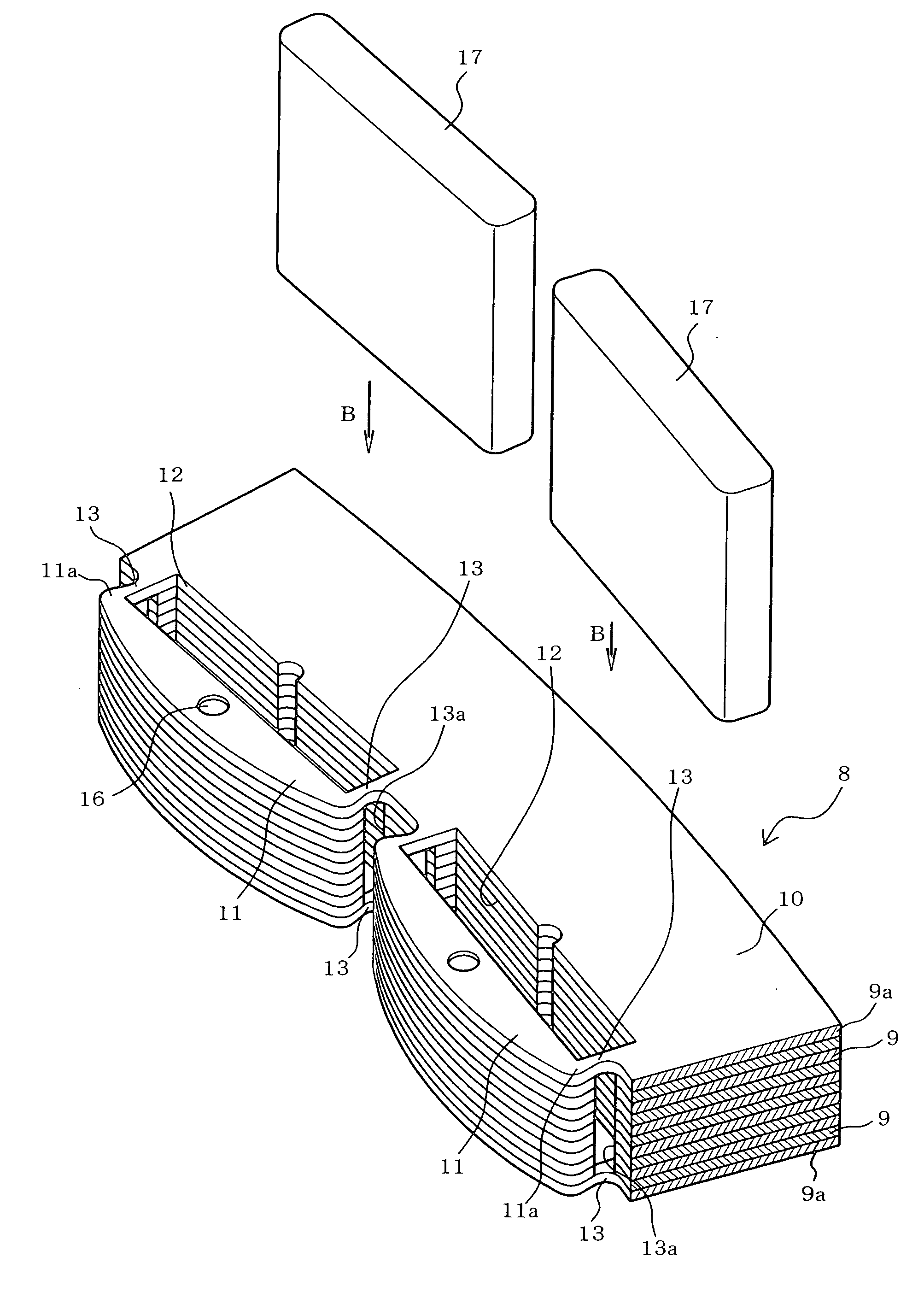
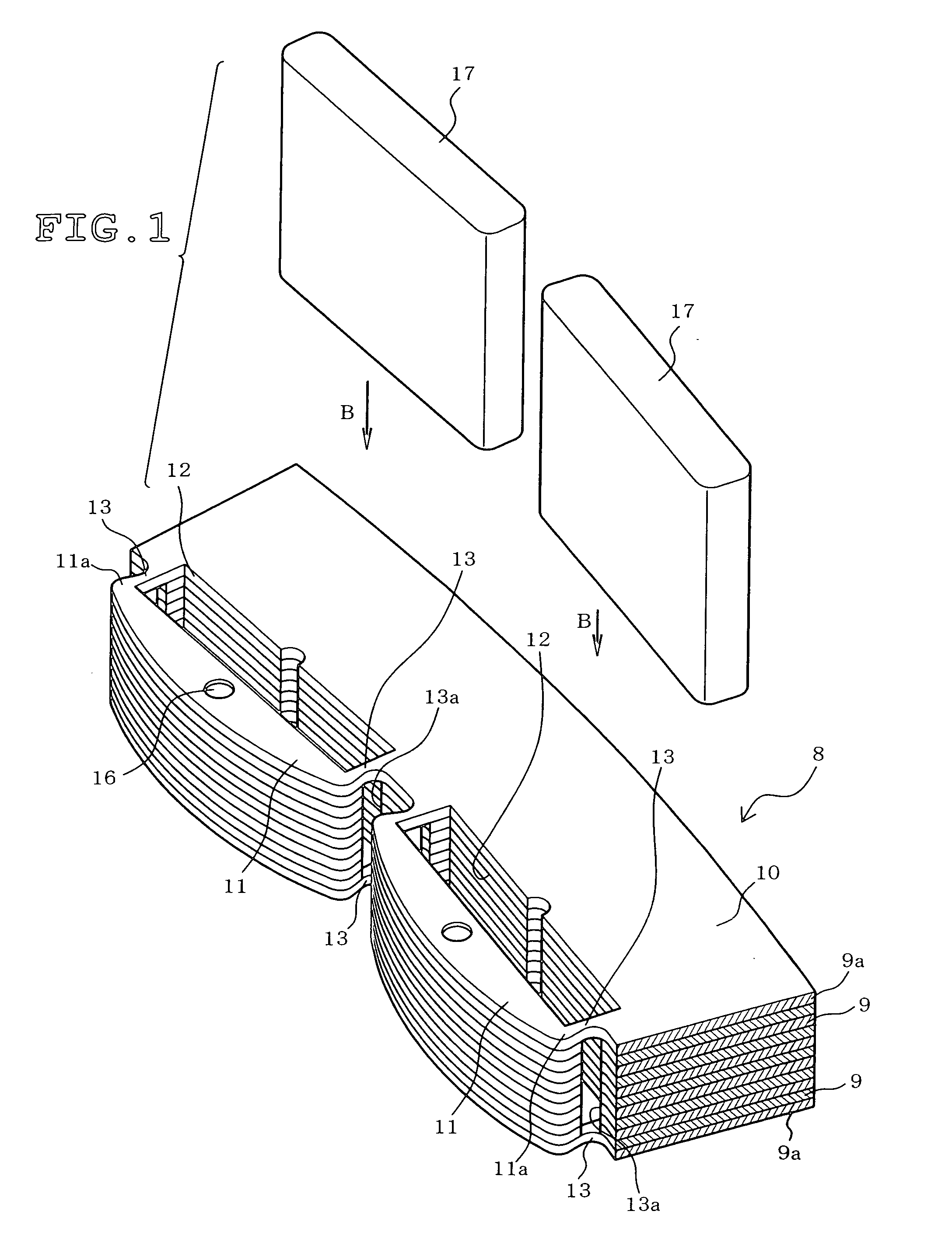
[0025]A rotor 6 has a magnetic frame 7 formed as a cylindrical container with an opened top. An annular wall 7a is provided in the opened side of the outer periphery of the frame 7, and a rotor core 8 is disposed along the inner periphery of the annular wall 7a. The rotor core 8 is formed by stacking a plurality of blanks 9 of steel sheet (electromagnetic steel sheet) Z (refer to FIG. 3). The method of manufacturing the rotor core 8 will be detailed afterwards.

[0026]FIG. 1 illustrates the structure of the rotor core 8 and a method of inserting a permanent magnet 17 for...

Example

[0040]Next, a second embodiment of the present invention will be described with reference to FIG. 9.

[0041]FIG. 9 is a planar illustration of the positioning of the blank 9b and the blanking blade 15c and portions that are identical to FIG. 6 have been identified with the same reference symbols.

[0042]In the manufacturing steps of a blank 9b of the present embodiment, the caulking portion 16 is initially formed in the caulking step of step S1. At this point, the bridge 13 (refer to FIG. 6) is not cut. Then, after the insertion hole blanking step of step S2, the blank 9b is blanked while a bridge 20 is formed by a projection 15cb of the blanking blade 15c in the final blanking step of step S3. In contrast to the bridge 13 illustrated in FIG. 6, the width of the bridge 20 is narrowed to enable magnetic saturation. Thus, in the present embodiment, only the blank 9b is stacked in the stacking step of step S4 to form the rotor core 8.

[0043]According to the present embodiment, the magnetic ...


PUM

PropertyMeasurementUnit
Fractionaaaaaaaaaa
Lengthaaaaaaaaaa
Magnetismaaaaaaaaaa

Abstract

A rotor core of a rotating electrical machine formed by stacking a plurality of blanks blanked from a steel sheet, the blank having a yoke, a magnetic pole portion confronting the yoke, and a magnet insertion hole positioned between the yoke and the magnetic pole portion, the magnetic pole portion having a projection projecting circumferentially at two circumferential sides thereof.

Description

TECHNICAL FIELD[0001]The present invention is directed to a rotor core for a rotating electrical machine formed by stacking a plurality of blanks obtained by blanking a steel sheet for forming a core and a method of manufacturing the same.BACKGROUND ART[0002]A rotating electrical machine, for example a permanent magnet electric motor (permanent magnet motor) of an outer rotor type, as disclosed in JP-A-H08-182282, includes a substantially cylindrical stator having a slot containing a coil therein and a rotor surrounding the stator via an air gap so as to confront the stator. A plurality of magnetic pole permanent magnets in a circumferential shape is secured along the inner peripheral surface of the rotor by an adhesive, for example, thereby constituting a magnetic pole.DISCLOSURE OF THE INVENTIONProblem to be Overcome by the Invention[0003]Nd magnet (neodium magnet), SmFe (samarium iron magnet) and the like, are known for their outstanding magnetic characteristics and are thus used...

Claims


Application Information

Patent Timeline
IPC IPC(8): H02K1/27H02K15/03H02K1/22H02K15/02
CPCH02K1/2786Y10T29/49009Y10T29/49075Y10T29/49012Y10T29/49078H02K1/2791H02K15/03H02K2213/03H02K1/279H02K15/12H02K21/22H02K2201/09
Inventor SHIGA, TSUYOSHISHIBATA, NOBORU
Owner TOSHIBA LIFESTYLE PROD & SERVICES CORP
Why Eureka
Try Eureka