Energy harvesting from multiple piezoelectric sources

a piezoelectric generator and energy harvesting technology, applied in piezoelectric/electrostrictive/magnetostrictive devices, piezoelectric/electrostriction/magnetostriction machines, electrical equipment, etc., can solve the problem of less energy available for storage, low efficiency, and the ability to only handle one piezoelectric generator at a time. traditional single circuits can only handle one piezoelectric generator at a time, so as to achieve minimal or no energy energy energy loss

Inactive Publication Date: 2008-10-16
ADVANCED CERAMETRICS
View PDF14 Cites 73 Cited by
  • Summary
  • Abstract
  • Description
  • Claims
  • Application Information

AI Technical Summary

Benefits of technology

[0013]According to another aspect of the present invention, the multiple power piezoelectric power harvesting system may be compatible to all types of energy harvesting / scavenging circuits. This enables the multiple piezoelectric generator, power harvesting system to efficiently and cost effectively extract electric energy from multiple piezoelectric generator sources with minimal or no energy loss.
[0014]Since multiple piezoelectric generators can be used independently without energy loss, each piezoelectric transducer can be tuned to a specific frequency, which results in a multi-frequency, multi-functional energy harvester and / or a single broadband harvester.

Problems solved by technology

However, if multiple piezoelectric materials are attached to the same circuit in an attempt to produce more electric energy, the energy loss will be very high and there will be less energy stored in the capacitors than if a single piezoelectric transducer was used.
Also, further losses occur due to the destructive electric signal interference produced from each piezoelectric transducer, resulting in less energy available for storage.
For these reasons, traditional single circuits can only handle one piezoelectric generator at a time.
Also, these traditional single circuit devices are very expensive because each contains its own power conditioning and storage circuitry.

Method used


Image

  • Energy harvesting from multiple piezoelectric sources
  • Energy harvesting from multiple piezoelectric sources
  • Energy harvesting from multiple piezoelectric sources

Examples


Embodiment Construction

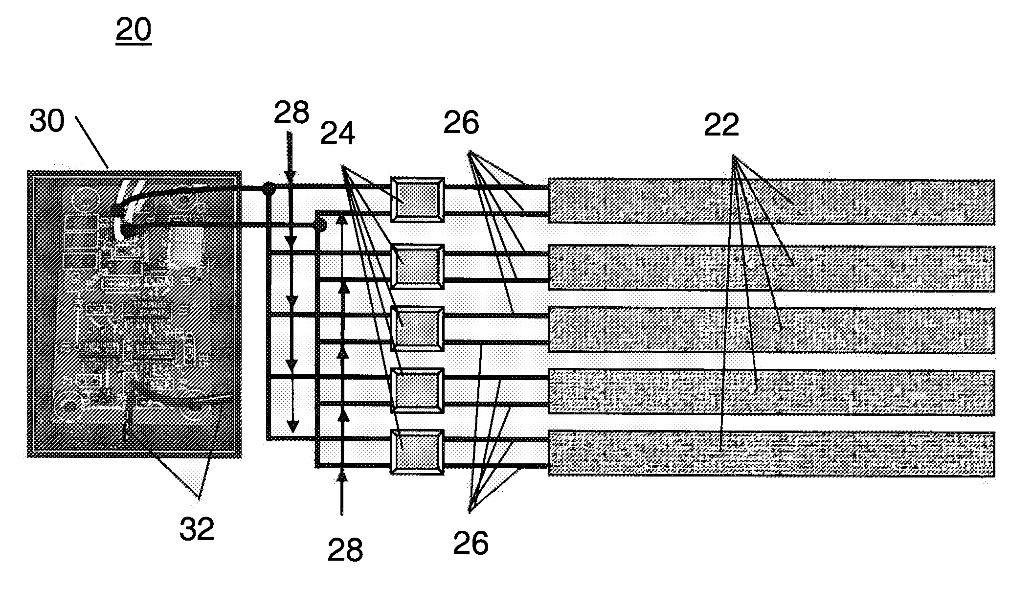
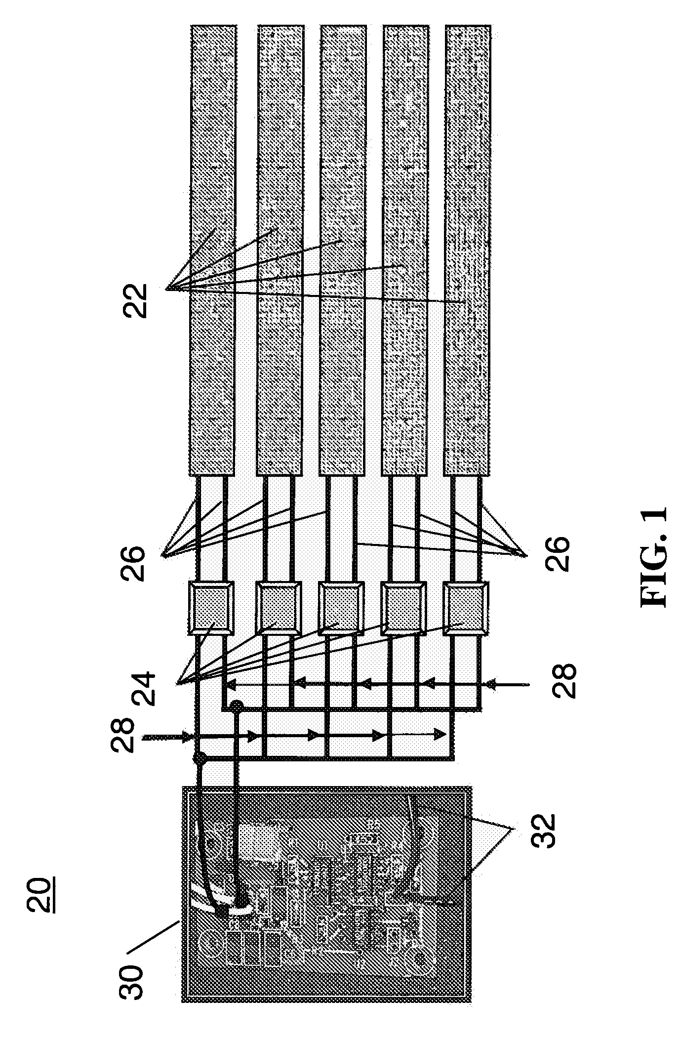
[0026]The following is a description of several exemplary embodiments of systems and methods for harvesting electrical energy from ambient or waste mechanical energy using multiple energy generators (e.g., piezoelectric generators) with minimal or no energy loss. Energy harvesting is the process by which energy is captured and stored and includes the conversion of ambient energy into usable electrical energy. Energy harvesting generators are devices that convert mechanical energy into electrical energy. Piezoelectric energy harvesting converts mechanical energy to electric energy by stressing a piezoelectric material. This stress in a piezoelectric material causes a charge separation across the device, producing an electric field and consequently a voltage drop proportional to the stress applied. Systems and methods according to embodiments of the present invention include multiple energy generators (e.g., any generators that produce an alternating current (AC)) connected to a singl...


PUM


Abstract

Energy harvesting systems and methods that use multiple piezoelectric generators connected to the same energy harvesting circuit with minimal or no energy loss. The piezoelectric energy harvesting system may include individual diode bridge circuits electrically connected to the outgoing wires from each piezoelectric generator. The piezoelectric energy harvesting system may include multiple subsystems each having one or more individual diode bridges electrically connected to the outgoing wires from multiple piezoelectric generators. Multiple subsystems, each having multiple piezoelectric generators and a diode bridge, may be electrically connected to the same energy harvesting circuit. The use of multiple piezoelectric generators connected to the same energy harvesting circuit results in improved energy harvesting capabilities, and a simplified and low cost energy harvesting system.

Description

TECHNOLOGY FIELD[0001]The present invention generally relates to the field of energy harvesting. More particularly, the present invention relates to systems and methods for electrical energy harvesting from multiple piezoelectric sources.BACKGROUND[0002]Piezoelectric materials are used in many applications for actuation, sensing, and electric energy harvesting. Piezoelectricity is the ability of crystals to generate a voltage in response to applied mechanical stress. As such, a mechanical stress applied on a piezoelectric material creates an electric charge. Piezoceramics will give off an electric pulse even when the applied pressure is as small as sound pressure. This phenomenon is called the direct piezoelectric effect and is used in sensor applications such as microphones, undersea sound detecting devices, pressure transducers, and electric energy harvesting to power other electronic devices. Piezoelectric materials can also function quite opposite in the converse piezoelectric e...

Claims


Application Information

Patent Timeline
Patent Type & Authority Applications(United States)
IPC IPC(8): H02N2/18H02J3/00
CPCG01L1/16H02N2/18
Inventor MOHAMMADI, FARHADCASS, RICHARD B.
Owner ADVANCED CERAMETRICS
Why Eureka
Try Eureka