Evanescent Mode Resonator Including Tunable Capacitive Post

a capacitive post and resonator technology, applied in the direction of waveguide devices, basic electric elements, electrical apparatus, etc., can solve the problem of difficult integration with other millimeter wave integrated circuits

Inactive Publication Date: 2008-10-16
PACIFIC COAST FEATHER COMPANY +1
View PDF2 Cites 35 Cited by
  • Summary
  • Abstract
  • Description
  • Claims
  • Application Information

AI Technical Summary

Problems solved by technology

Further, known evanescent mode filters are generally based on waveguide components, and are therefore, difficult to integrate with other millimeter wave integrated circuits.

Method used


Image

  • Evanescent Mode Resonator Including Tunable Capacitive Post
  • Evanescent Mode Resonator Including Tunable Capacitive Post
  • Evanescent Mode Resonator Including Tunable Capacitive Post

Examples


Embodiment Construction

[0012]The following discussion of the embodiments of the invention directed to a tunable evanescent mode resonator and method for making same is merely exemplary in nature, and is in no way intended to limit the invention or its applications or uses.

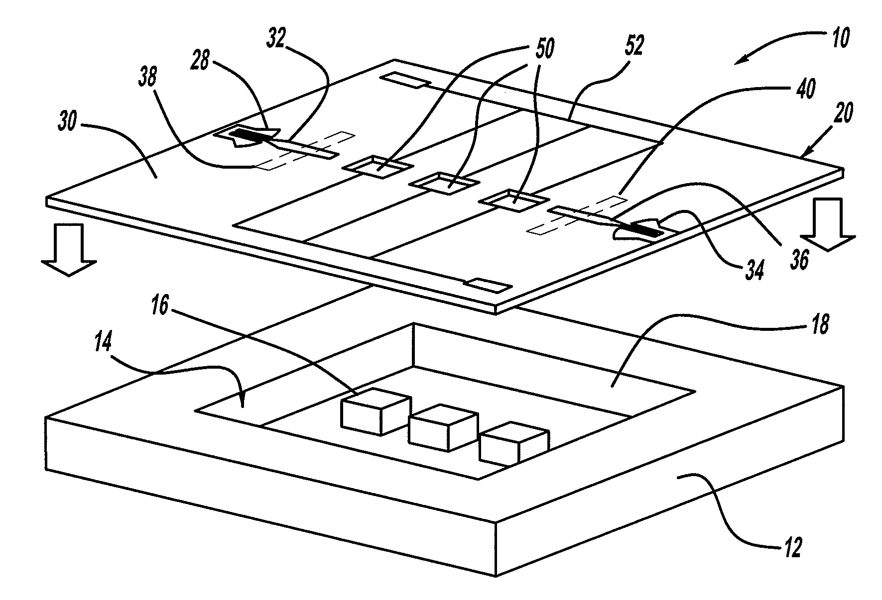
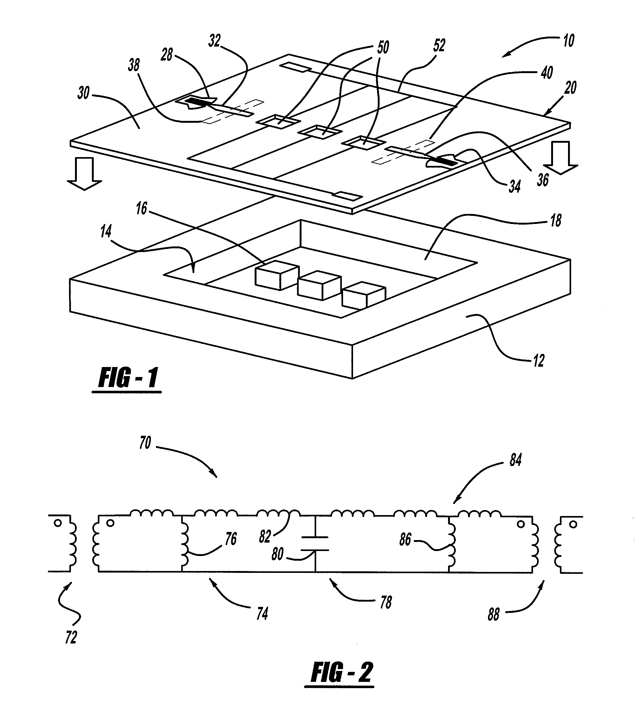
[0013]FIG. 1 is a blown-apart perspective view of an evanescent mode filter 10, according to an embodiment of the present invention. The filter 10 may have application for frequencies of GHz and above. The filter 10 includes a relatively thick base substrate layer 12 having a cavity 14 formed therein. Any suitable semiconductor micro-machining process can form the cavity 14. A series of capacitive posts 16 are provided within the cavity 14 to tune the filter 10 to the desired frequency in a manner that is well understood to those skilled in the art. Although the capacitive posts 16 are show here as being square, the invention contemplates any shape post suitable for an evanescent mode filter, including, but not limited to, square, rectan...


PUM


Abstract

An evanescent mode resonator including a cavity formed in a substrate of semiconductor material. The resonator includes a capacitive post positioned within the cavity, and a tuning element positioned within the wall of the cavity proximate to the capacitive post, where a gap between the flexible element and the post sets the tuning of the resonator.

Description

BACKGROUND OF THE INVENTION[0001]1. Field of the Invention[0002]This invention relates generally to an evanescent mode resonator and, more particularly, to an evanescent mode resonator that employs a tunable capacitive post.[0003]2. Discussion of the Related Art[0004]Evanescent mode resonators that have a high-Q and low-loss characteristics are known in the art for various applications, such as for filtering RF signals at a receiver front end. A few resonators can be cascaded together to provide an RF filter. One known evanescent mode resonator is micro-machined in silicon, and includes a capacitive post positioned within a cavity in which the RF waves resonate. The size of the cavity, the size of the post and a gap between the post and the cavity wall set the resonant frequency and the quality factor (Q) of the resonator. The capacitive post lowers the resonant frequency of the cavity, which allows an RF signal of a certain frequency to resonate within an otherwise much smaller cav...

Claims


Application Information

Patent Timeline
Patent Type & Authority Applications(United States)
IPC IPC(8): H01P1/219
CPCH01P1/219
Inventor MARGOMENOS, ALEXANDROSKATEHI, LINDA P.B.
Owner PACIFIC COAST FEATHER COMPANY
Why Eureka
Try Eureka