Device and Method for the Contactless Determination of the Direction of Viewing

a technology of contactless determination and direction, applied in the field of contactless determination of the direction of viewing, can solve the problems of limiting the visual field, requiring extremely elaborate image processing, and high cost of established devices based on this principl

a technology of contactless determination and direction, applied in the field of contactless determination of the direction of viewing, can solve the problems of limiting the visual field, requiring extremely elaborate image processing, and high cost of established devices based on this principl

US20080252850A1Inactive Publication Date: 2008-10-16ELDITH

Image

  • Device and Method for the Contactless Determination of the Direction of Viewing
  • Device and Method for the Contactless Determination of the Direction of Viewing
  • Device and Method for the Contactless Determination of the Direction of Viewing

Examples


Embodiment Construction

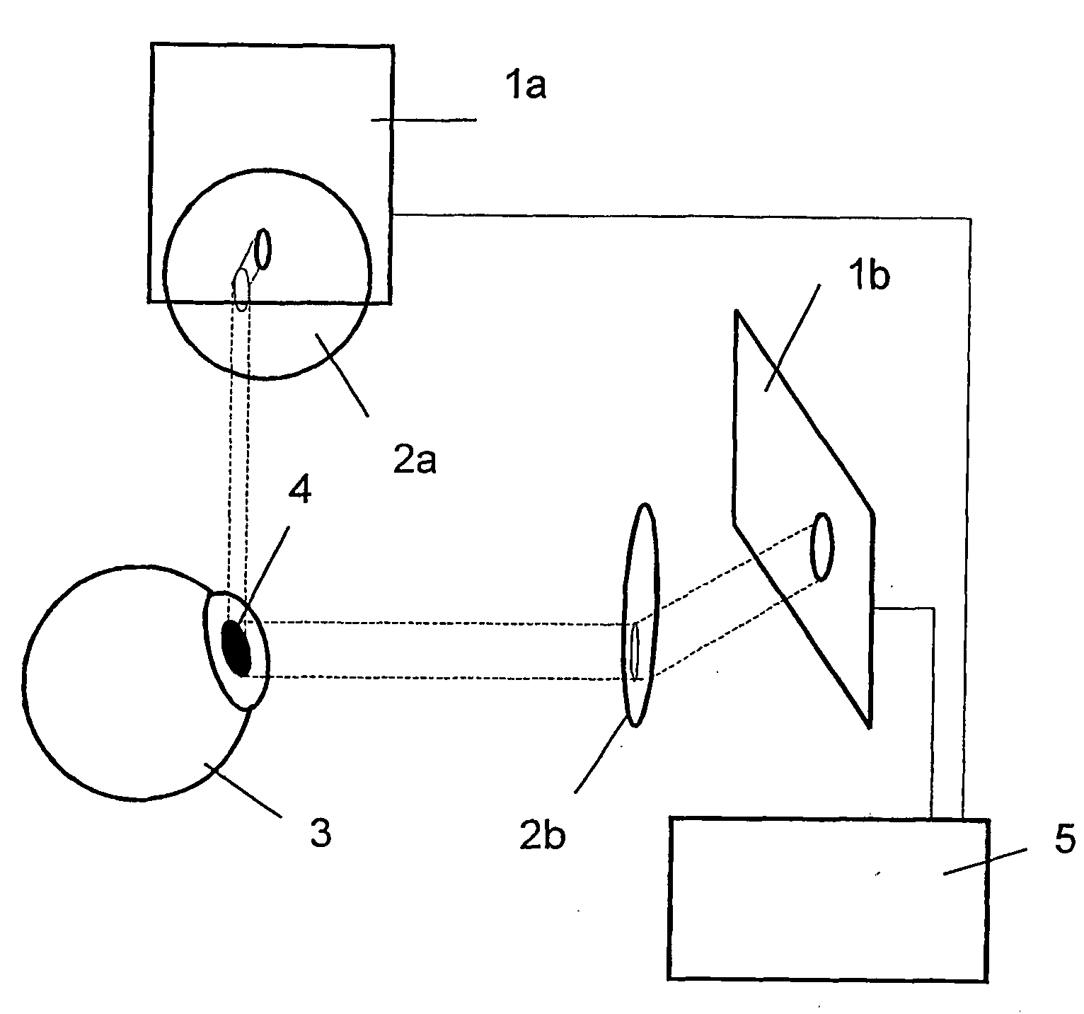
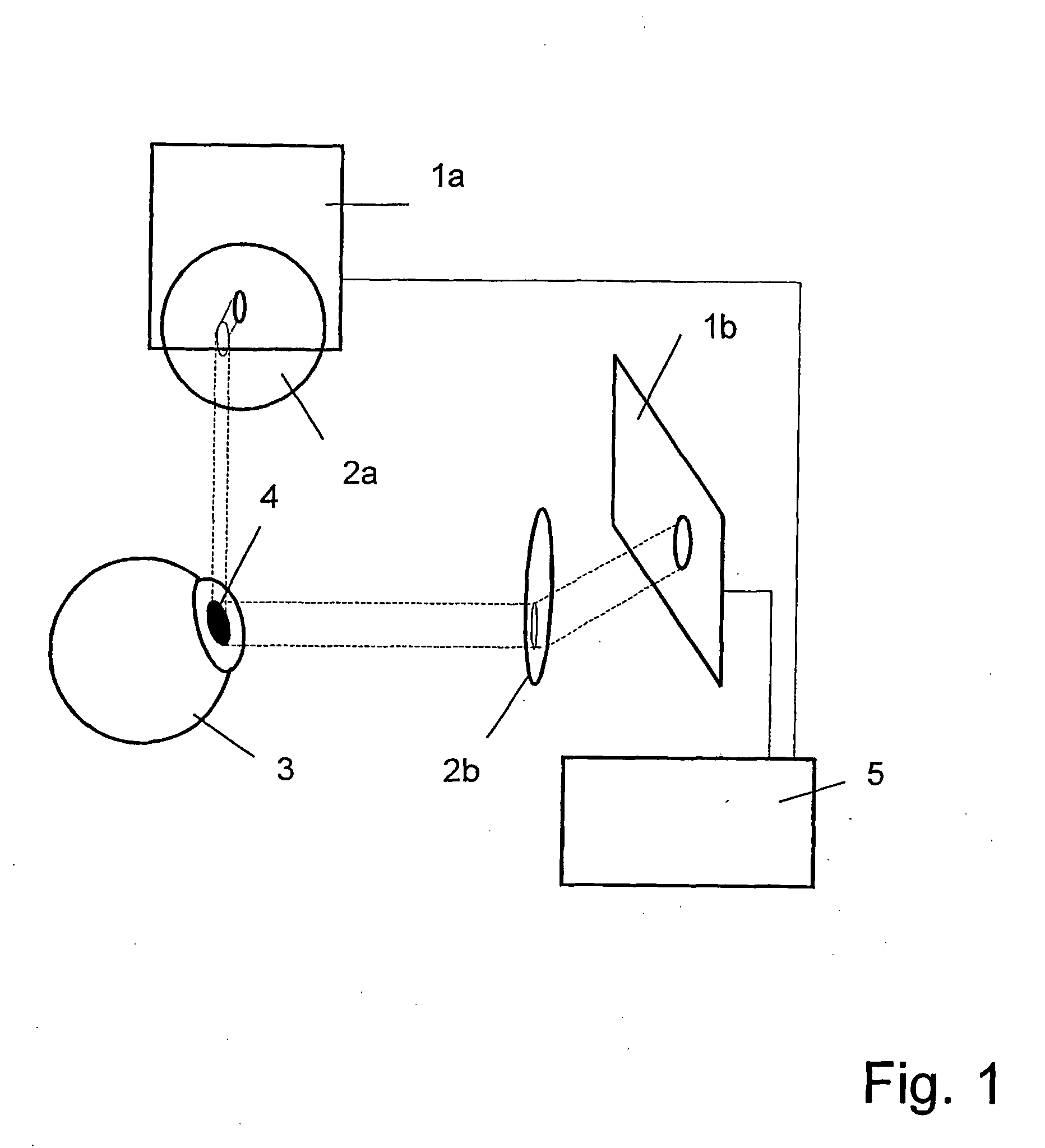
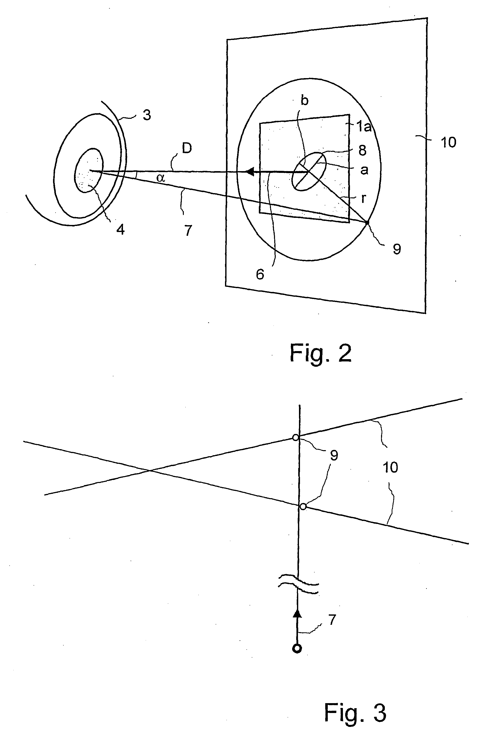
[0019]Referring to FIG. 1, the device comprises two cameras, each camera having its essential parts, the receiver surfaces 1a and 1b with their imaging optics 2a and 2b arranged in front. The cameras are located within a spatial reference system (coordinate system). The eye 2 is photographed from at least two spatial directions with simultaneous image recordings. The shape of the pupil 4 and the position on the receiver surfaces 1a and 1b are determined from the images and mathematically described. As can also be seen from FIG. 1, the cameras are connected to an image processing system 5. The surface normal 6 of the respective receiver surface 1a or 1b and the gaze direction vector 7, which is defined as the vector of the tangential surface of the pupil 4, enclose an angle α (FIG. 2). The pupil 4, which is round per se, is imaged as an ellipse 8 through this angle α. The ellipse 8 is characterized by its semimajor axis a and its semiminor axis b. The semimajor axis a corresponds exa...


PUM


Abstract

The invention is directed to a device and a method for the contactless determination of the actual gaze direction of the human eye. They are applied in examinations of eye movements, in psychophysiological examinations of attentiveness to the environment (e.g., cockpit design), in the design and marketing fields, e.g., advertising, and for determining ROIs (regions of interest) in two-dimensional and three-dimensional space.

Description

CROSS-REFERENCE TO RELATED APPLICATIONS[0001]This application claims priority of International Application No. PCT / DE2005 / 001657, filed Sep. 19, 2005 and German Application No. 10 2004 046 617.3, filed Sep. 22, 2004, the complete disclosures of which are hereby incorporated by reference.BACKGROUND OF THE INVENTION[0002]a) Field of the Invention[0003]The invention is directed to a device and a method for the contactless determination of the actual gaze direction of the human eye. They are applied in examinations of eye movements, in psychophysiological examinations of attentiveness to the environment (e.g., cockpit design), in the design and marketing fields, e.g., advertising, and for determining ROIs (regions of interest) in two-dimensional and three-dimensional space.[0004]b) Description of the Related Art[0005]The prior art discloses various devices and methods by which eye gaze direction and gaze point can be determined in a contactless manner.[0006]Corneal reflection method: In...

Claims


Application Information

Patent Timeline
16 Oct 2008
Publication
US20080252850A1
IPC
A61B3/113
CPC
A61B3/113; G06V40/19; G06V20/597
Inventors
PLAGWITZ, KAI-UWE; HUSAR, PETER