System and method using fluorescence to examine within a patient's anatomy

Inactive Publication Date: 2008-10-16
ETHICON ENDO SURGERY INC
View PDF100 Cites 12 Cited by
  • Summary
  • Abstract
  • Description
  • Claims
  • Application Information

AI Technical Summary

Benefits of technology

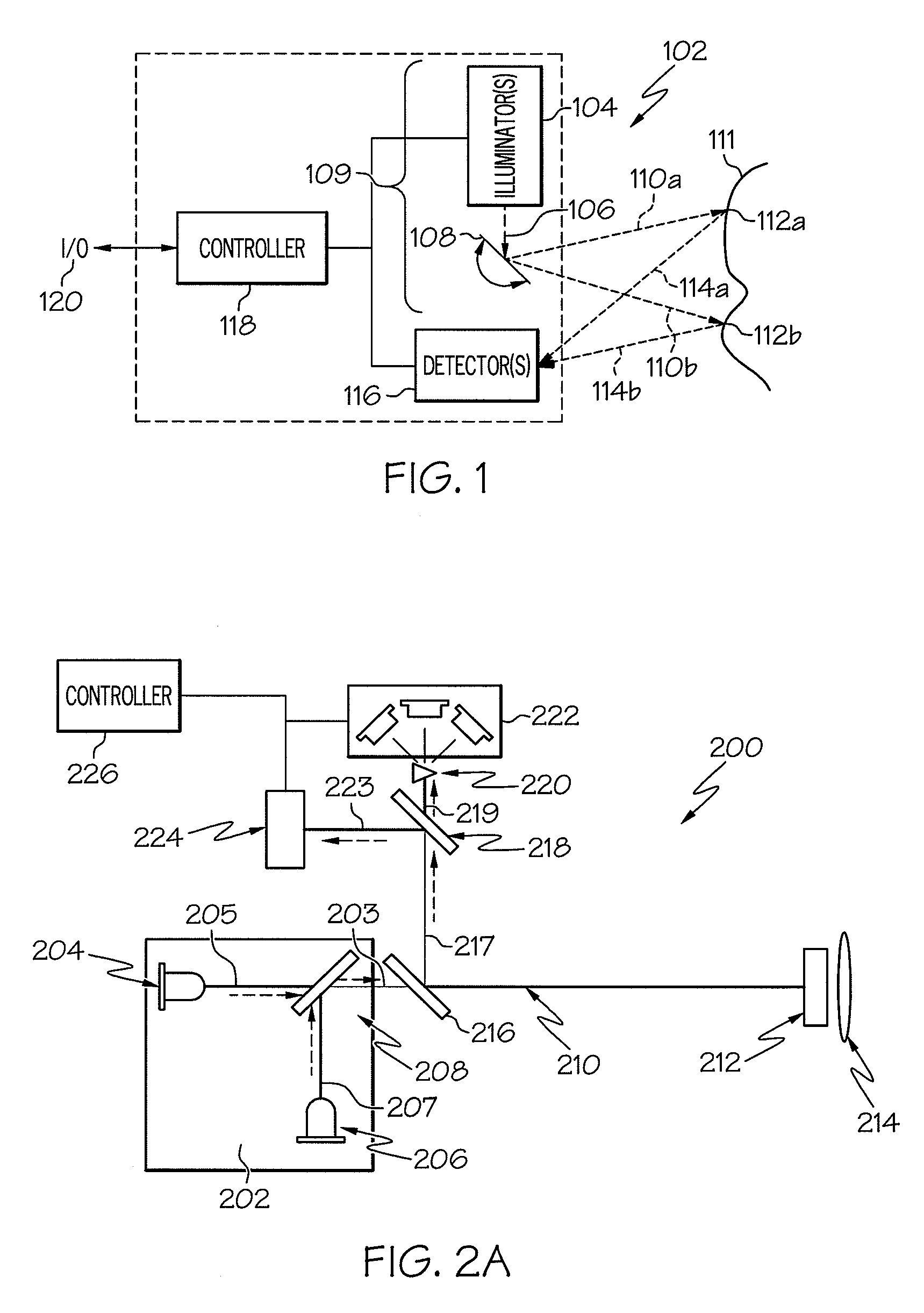
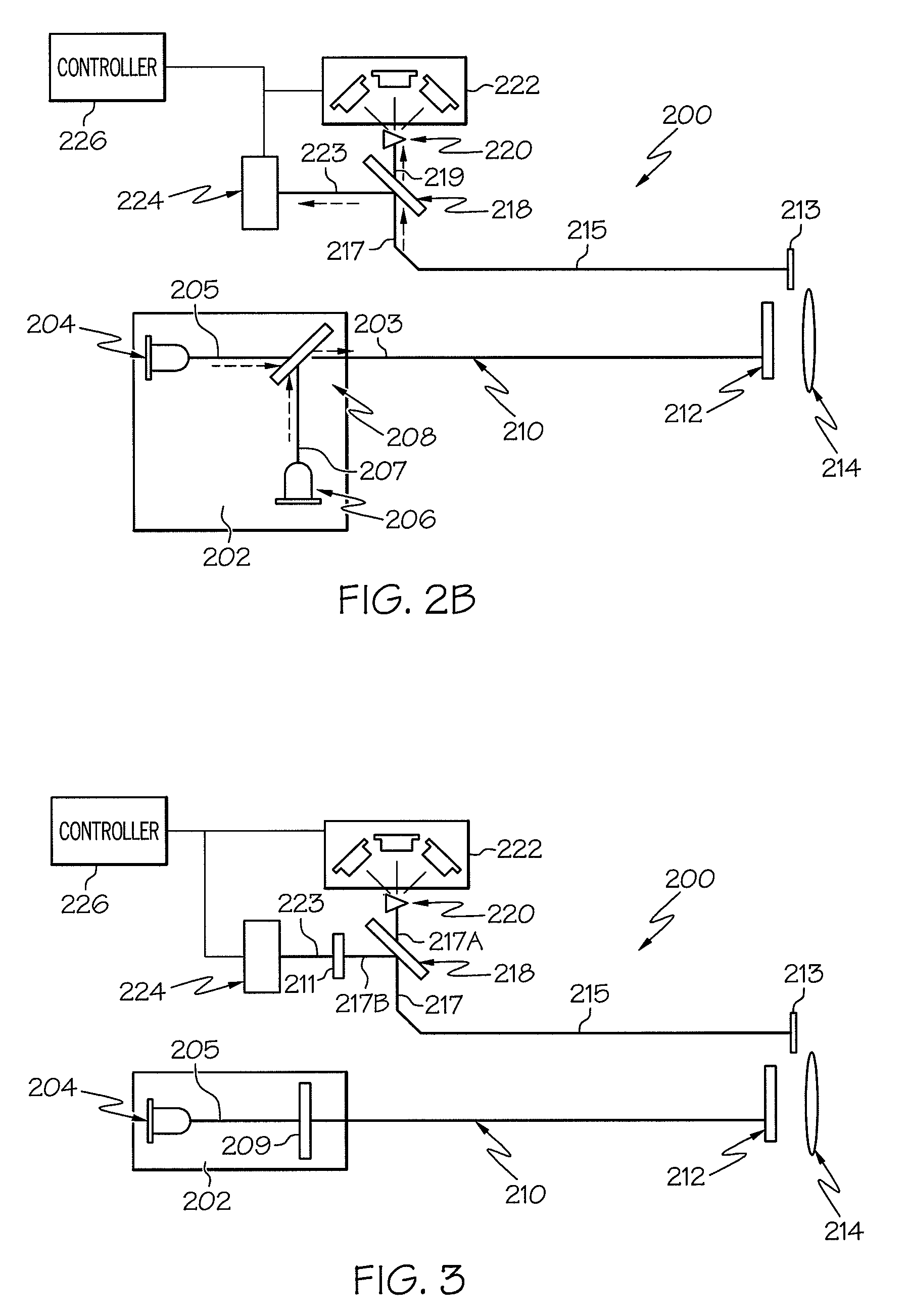
[0011]The scanning beam assembly has an optical pathway that is largely a single optical fiber that can transmit a combined beam of radiation along its length. This optical architecture has the advantage of allowing a large amount of imaging radiation, excitat

Problems solved by technology

However, even with a SBI there are some the anatomy structures within the anatomy that

Method used


Image

  • System and method using fluorescence to examine within a patient's anatomy
  • System and method using fluorescence to examine within a patient's anatomy
  • System and method using fluorescence to examine within a patient's anatomy

Examples


Embodiment Construction

[0015]Before explaining the several embodiments of the present invention in detail, it should be noted that each embodiment is not limited in its application or use to the details of construction and arrangement of parts and steps illustrated in the accompanying drawings and description. The illustrative embodiments of the invention may be implemented or incorporated in other embodiments, variations and modifications, and may be practiced or carried out in various ways. Furthermore, unless otherwise indicated, the terms and expressions employed herein have been chosen for the purpose of describing the illustrative embodiments of the present invention for the convenience of the reader and are not for the purpose of limiting the invention.

[0016]It is further understood that any one or more of the following-described embodiments and examples can be combined with any one or more of the other following-described embodiments or examples.

[0017]In one embodiment, the present invention provi...


PUM


Abstract

A system for examining an area of a patient's anatomy that comprises a probe capable of fluorescing, and a scanning beam assembly that scans the probe with a beam of excitation radiation and detects the probe's fluorescence. The scanning beam assembly including a radiation source capable of emitting one or more wavelengths of radiation that are capable of exciting the probe and causing the probe to fluoresce, a scanning device that directs the radiation onto a field-of-view to create a scan of the field-of-view, a detector to detect radiation returned from the field-of-view, and a controller to convert the detected radiation into a displayable fluorescence image.

Description

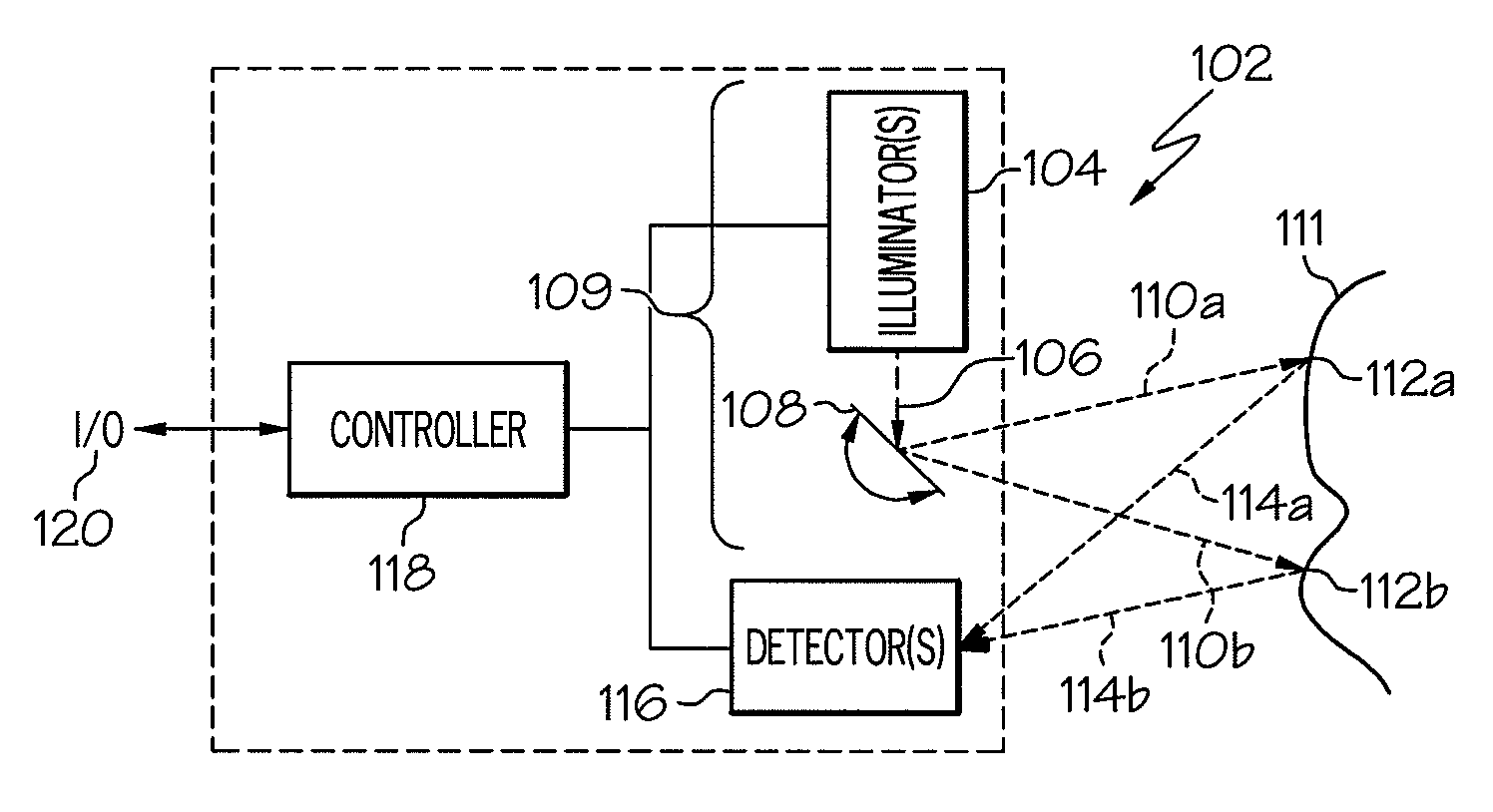
FIELD OF THE INVENTION [0001]The present invention is related generally to imaging fluorescence in the anatomy, and more particularly to medical applications of fluorescent imaging of the anatomy using a scanning beam assembly.BACKGROUND OF THE INVENTION [0002]U.S. Published Application 2005 / 0020926 discloses a scanning beam imager (SBI) which is reproduced in FIG. 1 herein. This imager can be used in applications in which cameras have been used in the past. In particular it can be used in medical devices such as video endoscopes, laparoscopes, etc.[0003]FIG. 1 shows a block diagram of one example of a scanned beam imager 102. An illuminator 104 creates a first beam of light 106. A scanner 108 deflects the first beam of light across a field-of-view (FOV) to produce a second scanned beam of light 110, shown in two positions 110a and 110b. The scanned beam of light 110 sequentially illuminates spots 112 in the FOV, shown as positions 112a and 112b, corresponding to beam positions 110a...

Claims


Application Information

Patent Timeline
IPC IPC(8): A61B6/00
CPCA61B5/0071A61B5/0075A61B5/0084A61B5/0086A61B5/415A61B5/418
Inventor DUNKI-JACOBS, ROBERT J.YAZDI, YOUSEPHWEIR, MICHAEL P.RITCHIE, PAUL G.YOUMANS, DAVID C.GILL, ROBERT P.
Owner ETHICON ENDO SURGERY INC
Why Eureka
Try Eureka