Fluid flow control system having capillary fluid flow restrictor

a technology of fluid flow control and restrictor, which is applied in water supply installation, process and machine control, instruments, etc., can solve the problems of contaminants falling out of the fluid solution, filtering contaminants into the chamber, and affecting the flow of fluid into the chamber

Active Publication Date: 2008-10-23
CAREFUSION 303 INC
View PDF28 Cites 17 Cited by
  • Summary
  • Abstract
  • Description
  • Claims
  • Application Information

AI Technical Summary

Benefits of technology

[0024]In accordance with method aspects of the invention, there is provided a method for restricting the flow of medicament through a fluid supply tube comprising pumping medicament into the fluid supply tube at a first instantaneous velocity, slowing the velocity of medicament through the fluid supply tube at a point downstream to a second instantaneous velocity that is less than the first such that contaminants in the medicament fall out of solution and are separated from the liquid of the medicament, and conducting the liquid of the medicament from the point where the contaminants are separated preventing the contaminants from further downstream flow.

Problems solved by technology

The relative smallness of the inner cross-section of the capillary tube as compared to the inner cross-sections of the chamber and the supply tube results in filtering of contaminants into the chamber.
In addition, the chamber volume resulting from the selected length of the chamber and the selected chamber inner cross-section slows the instantaneous velocity of the fluid from the supply tube so that contaminants will fall out of solution of the fluid and into the chamber.

Method used


Image

  • Fluid flow control system having capillary fluid flow restrictor
  • Fluid flow control system having capillary fluid flow restrictor
  • Fluid flow control system having capillary fluid flow restrictor

Examples


Embodiment Construction

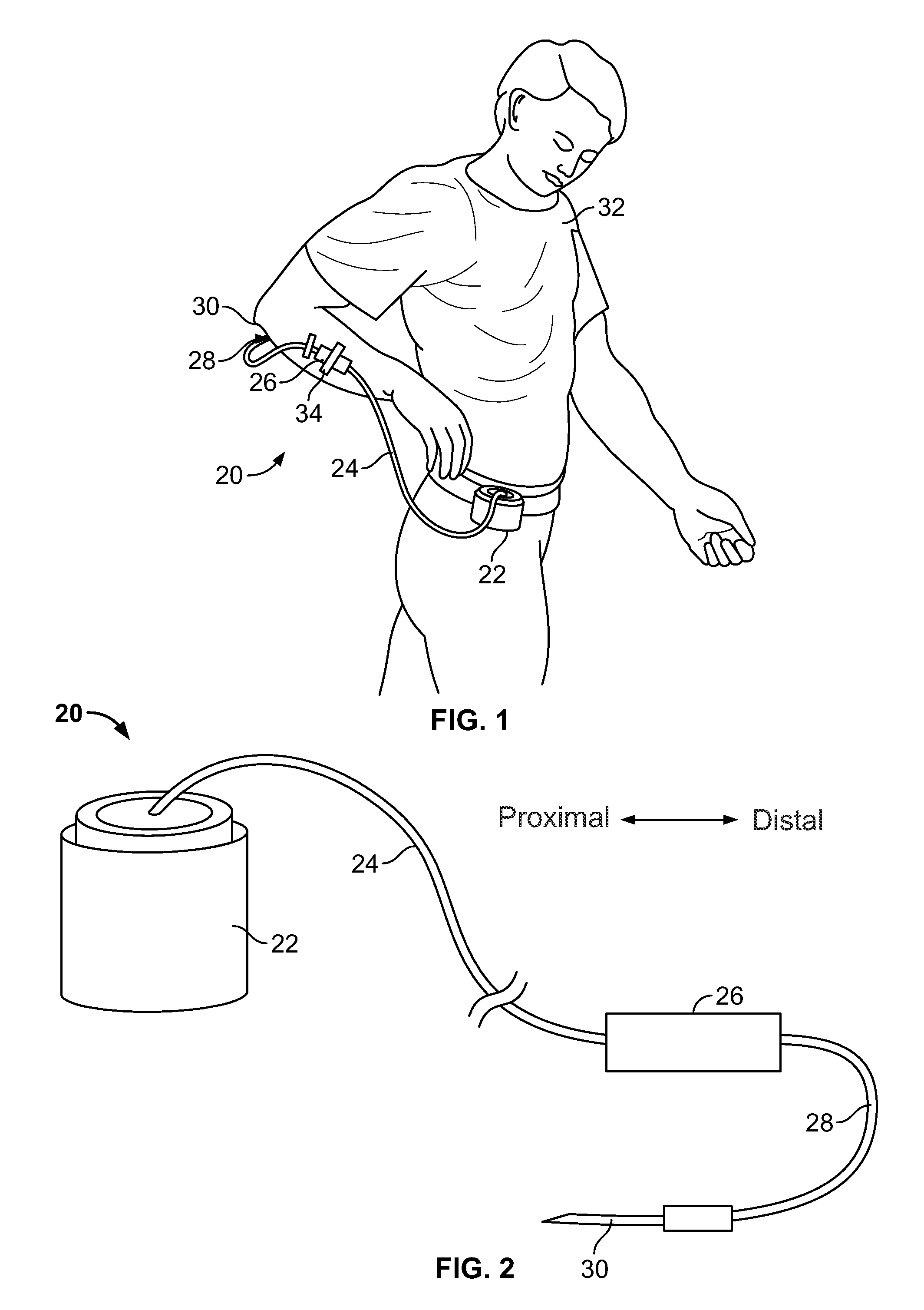
[0033]Referring now to the drawings in more detail in which like reference numerals refer to like or corresponding devices among the views, there is shown in FIGS. 1 and 2 a view of an embodiment of an infusion system 20 having a pump 22, a medicament supply tube segment or pump-side tube segment 24 from the pump, a fluid flow rate restrictor 26, a patient delivery tube segment or patient-side tube segment 28, and a sharp cannula 30 for inserting into the patient to perform the infusion. In FIG. 1, it will be noted that the restrictor has been affixed to the patient 32 with tape 34 to stabilize the position of the cannula and control the temperature of fluid entering the restrictor assembly. This approach is meant to provide a broad illustration only and not meant to be restrictive of the use of the invention. Other techniques well known to those skilled in the art for mounting pumps to or with a patient, puncturing the patient, and stabilizing a tube, restrictor, or other devices m...


PUM


Abstract

A fluid flow rate control system and method comprises a capillary tube having a proximal end that projects into a chamber with a cross-sectional area that is larger than or equal to the fluid supply tube's cross-sectional area. The inner cross-sectional area of the capillary tube is configured less than the inner cross-sectional area of the chamber. The chamber has a volume large enough to slow the fluid conducted to it by the upstream fluid line to permit contaminants to fall out of solution. In another aspect, a sleeve is used to mount the capillary tube into the chamber. The sleeve provides a mounting surface for tube segments from the pump and downstream of the capillary restrictor.

Description

BACKGROUND OF THE INVENTION[0001]The invention generally relates to systems and methods for controlling the infusion of medical fluids and, more particularly, to a fluid flow restrictor placed in an infusion line to achieve a more uniform rate of flow through that line while reducing the possibility of contaminants being conducted.[0002]Infusion of fluids is one of the most widespread procedures in medicine. Infusion systems deliver liquid therapeutic substances (e.g. drugs in solution, saline, nutrients) to patients typically through veins and arteries, but also into interstitial spaces as well. Every infusion is driven by some source of pressure. Two common sources of fluid pressure for causing the infusion of medical fluids into a patient are gravity and positive pressure infusion pumps. The medical fluids are typically delivered through sterile, single-use, disposable fluid administration sets that comprise tubing and a cannula or catheter and perhaps an administration port or p...

Claims


Application Information

Patent Timeline
Patent Type & Authority Applications(United States)
IPC IPC(8): A61M5/168F15D1/02
CPCA61M5/141A61M5/14244A61M5/16804A61M5/16877Y10T137/85978Y10T137/0318
Inventor WALBORN, JONATHAN
Owner CAREFUSION 303 INC
Why Eureka
Try Eureka