Nacelle assembly without lower bi-fi splitter

a technology of nacelle and splitter, which is applied in the direction of machines/engines, lighter-than-air aircraft, transportation and packaging, etc., can solve the problems of reducing engine efficiency, and achieve the effects of improving aerodynamic packaging, reducing drag in the bypass fan stream, and improving performan

Inactive Publication Date: 2008-10-23
UNITED TECH CORP
View PDF34 Cites 21 Cited by
  • Summary
  • Abstract
  • Description
  • Claims
  • Application Information

AI Technical Summary

Benefits of technology

[0005]The nacelle assembly according to the present invention includes separately movable fan cowl doors, thrust reverser doors, and core cowl doors. The thrust reverser doors and core cowl doors have separate thrust reverser door hinge lines and core cowl door hinge lines for independent operation to eliminate the requirement of a lower bi-fi splitter. The removal of the lower Bi-Fi splitter provides improved aerodynamic packaging with improved performance by reducing drag in the bypass fan stream.
[0006]The present invention therefore provides an engine nacelle arrangement which minimizes engine bypass fan steam flow.

Problems solved by technology

Although the bi-fi provides additional stiffness for the nacelle, the bi-fi splitter may partially block the bypass fan stream and reduce engine efficiency.

Method used


Image

  • Nacelle assembly without lower bi-fi splitter
  • Nacelle assembly without lower bi-fi splitter
  • Nacelle assembly without lower bi-fi splitter

Examples


Embodiment Construction

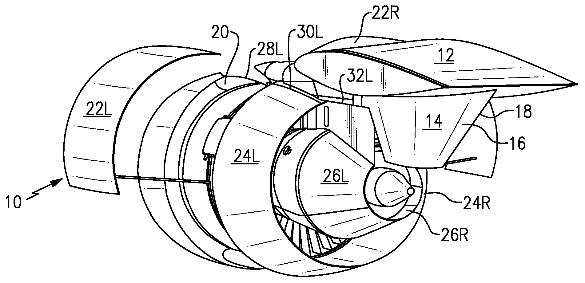
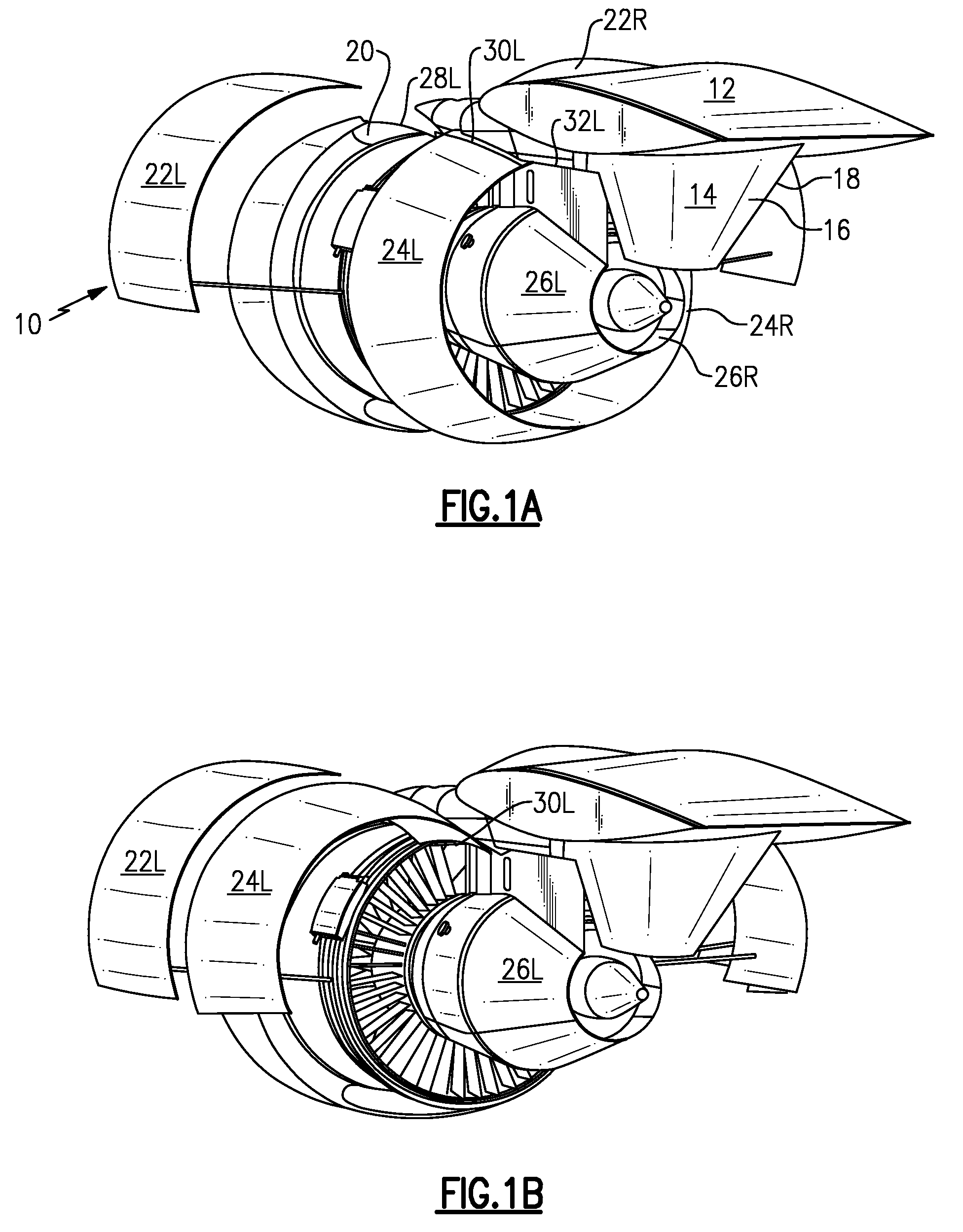
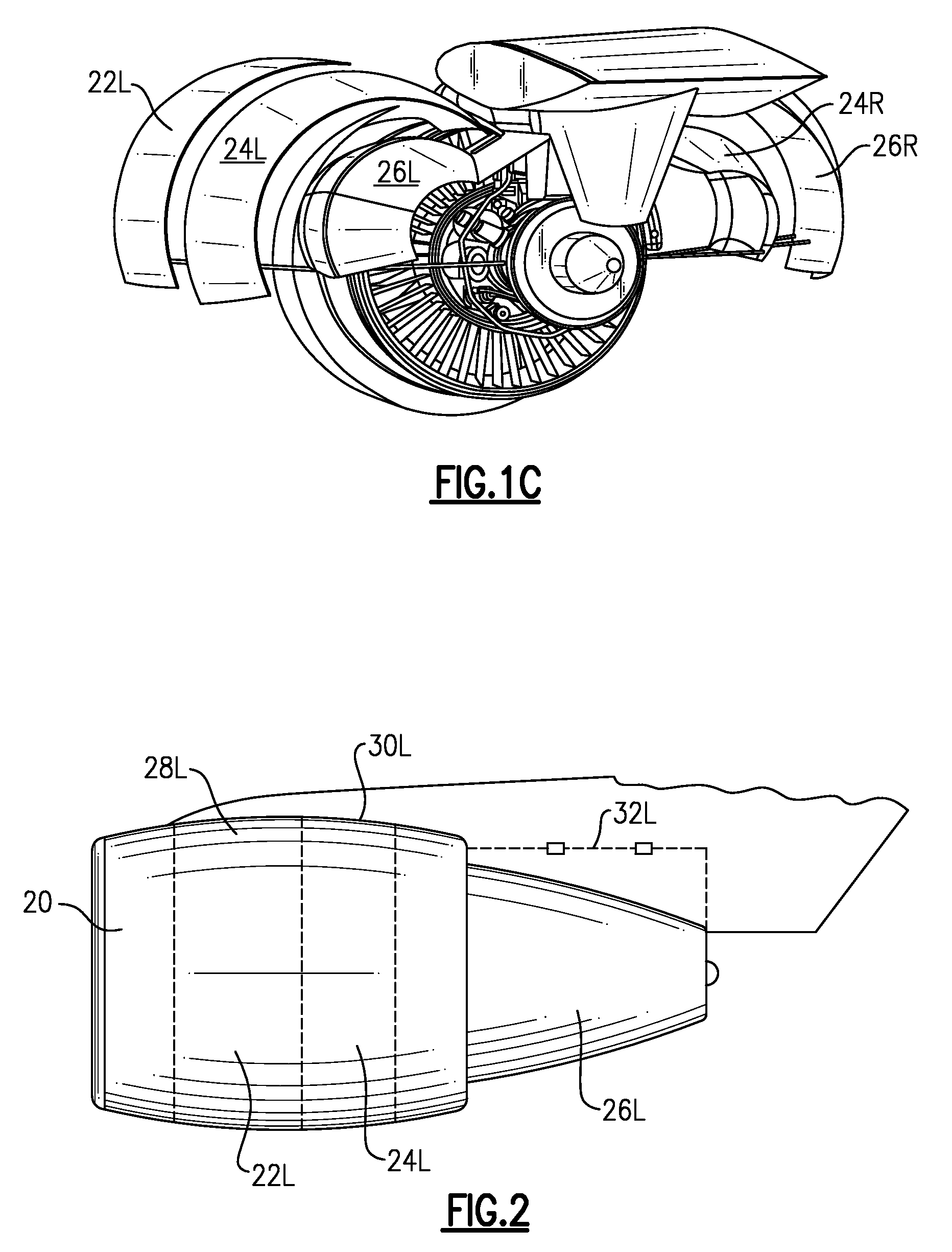
[0012]FIGS. 1A-1C schematically illustrates a gas turbine engine 10 of the axially flow, turbo fan type. Wing 12 of an aircraft includes a pylon or other support structure 14 which engages the engine 10. The pylon 14 has a first side 16 and a second side 18. A nacelle assembly 20 is mounted to the pylon 14 to circumscribe the engine 10 to support and position the engine 10 relative the aircraft wing 12.

[0013]The nacelle assembly 20 includes separately movable fan cowl doors 22L, 22R, thrust reverser doors 24L, 24R, and core cowl doors 26L, 26R. The core cowl doors 26L, 26R are located at least partially radially within the thrust reverser doors 24L, 24R. Each of the fan cowl doors 22L, 22R, thrust reverser doors 24L, 24R, and core cowl doors 26L, 26R are defined to hinge about a respective hinge line 28L, 28R, 30L, 30R, and 32L, 32R. It should be understood that the fan cowl door 22, the thrust reverser door 24, and the core cowl door 26 include both left hand (LH) and right hand (R...


PUM


Abstract

A nacelle assembly provides thrust reverser doors and core cowl doors with separate thrust reverser door hinge lines and core cowl doors hinge lines for independent operation to eliminate the requirement of a lower bi-fi splitter. The removal of the lower Bi-Fi splitter provides improved aerodynamic packaging with improved performance by reducing drag in the bypass fan stream.

Description

BACKGROUND OF THE INVENTION[0001]The present invention relates to aircraft engine nacelles, and more particularly to aircraft engine nacelles having thrust reverser cowl doors and core cowl doors which are independently hinged to eliminate a lower bi-fi splitter.[0002]Gas turbine engines are mounted on an aircraft by a support structure such as a pylon. A nacelle arrangement encloses the engine forming a shelter which is aerodynamically contoured to reduce drag. The nacelle arrangement is supported in part from the pylon and in part from the engine.[0003]Conventional nacelle arrangements include a removable metal and or composite cowling. The cowling includes a fan duct reverser cowl and a core cowl. The larger diameter fan duct reverser cowl and the smaller diameter core cowl are interconnected by a bi-fi wall. Although the bi-fi provides additional stiffness for the nacelle, the bi-fi splitter may partially block the bypass fan stream and reduce engine efficiency.[0004]Accordingly...

Claims


Application Information

Patent Timeline
Patent Type & Authority Applications(United States)
IPC IPC(8): B64D29/00B64C1/14
CPCB64D29/00F02K3/06F02K1/70
Inventor GUKEISEN, ROBERT L.MARSHALL, RICHARD M.
Owner UNITED TECH CORP
Why Eureka
Try Eureka