Rechargeable battery assembly and power system using same

a rechargeable battery and power system technology, applied in the field of rechargeable batteries, can solve the problems of degrading the performance of the entire battery set, and achieve the effect of simple devi

Active Publication Date: 2008-10-23
CHANGS ASCENDING ENTERPRISES CO LTD
View PDF7 Cites 66 Cited by
  • Summary
  • Abstract
  • Description
  • Claims
  • Application Information

AI Technical Summary

Benefits of technology

[0011]It is an object of the present invention to provide a simple device and method for charging a plurality of batteries electrically connected in a series circuit.

Problems solved by technology

The increase of voltage requires batteries to be connected in series.2. Problems associated with batteries in series are:a. when one battery has a lower capacity, the capacity of the overall set of batteries is dictated by the capacity of the battery of lower capacity;b. if the battery possessing the lower capacity can not be charged to full capacity during charging, the performance of the entire battery set will be degraded owing to the lower capacity battery.

Method used


Image

  • Rechargeable battery assembly and power system using same
  • Rechargeable battery assembly and power system using same
  • Rechargeable battery assembly and power system using same

Examples


example 1

Theoretical Demonstration of how Cell Equalization can be Achieved

Assumptions:

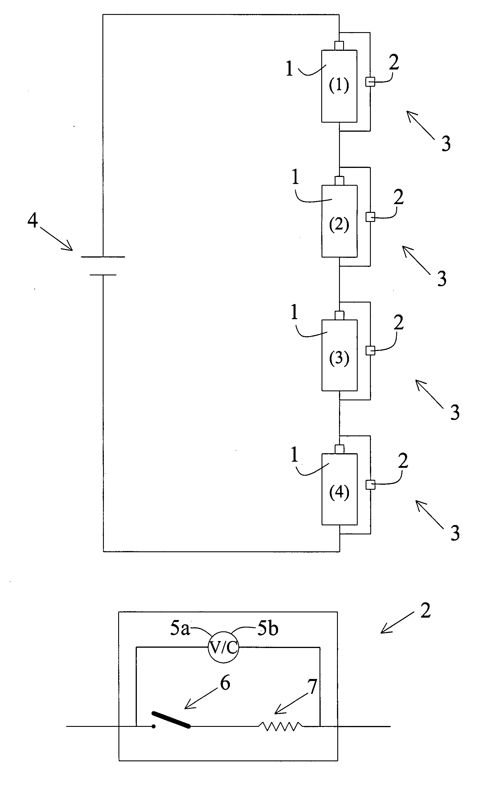
[0033]1. Four battery assemblies are connected in series as indicated in FIG. 2(a).[0034]2. Batteries (1), (3), (4) have internal resistance of 5 mOhm, battery (2) has an internal resistance of 10 mOhm.[0035]3. Batteries (1), (3), (4) have open circuit voltage of 3.3V, battery (2) has an open circuit voltage of 3.6V.[0036]4. For each battery assembly, a resistor of 1.0 Ohm is connected parallel to the battery.[0037]5. A power supply of 15V is applied to the four battery assemblies connected in series.

case 1 (

Calculation Case 1 (when Paralleled Resistors are all Open):

During charging of the four battery assemblies, the voltage of each battery can be represented as:[0038]Battery (1): V1=Vo1+I1R1, V1 is the voltage of the battery (1) during charging, Vo1 is the open circuit voltage of battery (1), I1 is the current passing through battery (1) and R1 is the internal resistance of the battery (1).[0039]Battery (2): V2=Vo2+I2R2,[0040]Battery (3): V3=Vo3+I3R3,[0041]Battery (4): V4=Vo4+I4R4,

Since no other resistors are connected, I1=I2=I3=I4=I

15=(V1+V2+V3+V4)=(Vo1+Vo2+Vo3+Vo4)+I(R1+R2+R3+R4)

15−(Vo1+Vo2+Vo3+Vo4)=I(R1+R2+R3+R4)

15−3.3−3.6−3.3−3.3=I(0.005+0.01+0.005+0.005)

I=60 Amp—The current that passes through each battery

case 2

Calculation Case 2, (when the Paralleled Resistor Circuit is Closed for Battery (2)):

Assume I′ is the current passing through the resistor and R′ is the resistance of the resistor.

Then,

[0042]

V2=I′R′, I′=V2 / R′

V2=Vo2+I2R2,

Considering the current balance: (I′+I2)=I1=I3=I4=I

So,

[0043]

V2=Vo2+(I−I′)R2=Vo2+(I−V2 / R′)R2

Rearrange, then we get

V2=(Vo2+IR2) / (1+R2 / R′)

Thus,

15=(V1+V2+V3+V4)=(Vo1+Vo3+Vo4)+I(R1+R3+R4)+(Vo2+IR2) / (1+R2 / R′)

So,

I=61.672(A),

V2=(Vo2+IR2) / (1+R2 / R′)=4.175(V),

I′=V2 / R′=4.175(A),

I2=I−I′=57.497(A)

If we substitute a resistor of 10 Ohm, then

I=60.168(A),

V2=Vo2+(I−V2 / R′)R2=4.1975(V),

I′=V2 / R′=0.4198(A),

I2=I−I′=59.748(A)

Conclusions from the Calculations:[0044]1. With regards to battery assembly of FIG. 2(a), when the switch of the resistor in the parallel circuit is closed, current flows through the resistor, and the charging current for battery (2) is decreased.[0045]2. While the switch of the paralleled resistor circuit is closed for the battery assembly of FIG. 2(a), the charging cu...


PUM


Abstract

A rechargeable battery, battery set or battery pack having a circuit or a plurality of circuits for providing self-discharging thereof electrically connected in parallel are used to form rechargeable battery assemblies and electric power supply systems for use in electric and hybrid vehicles and the like.

Description

[0001]This application claims priority of U.S. Provisional Applications entitled “Device for Charging Batteries in Series”, Ser. No. 60 / 923,747, and “The Novel Smart Battery Modules, and the System” mailed May 15, 2007.FIELD OF INVENTION[0002]The present invention is concerned with rechargeable batteries, and in particular with the recharging of rechargeable batteries.BACKGROUND OF THE INVENTION[0003]1. For batteries to be used for applications such as vehicle starter, electric bikes, electric motorcycles, electric or hybrid vehicles, etc, high voltage is essential owing to the increase of efficiency and the decrease of cost. The increase of voltage requires batteries to be connected in series.[0004]2. Problems associated with batteries in series are:[0005]a. when one battery has a lower capacity, the capacity of the overall set of batteries is dictated by the capacity of the battery of lower capacity;[0006]b. if the battery possessing the lower capacity can not be charged to full c...

Claims


Application Information

Patent Timeline
Patent Type & Authority Applications(United States)
IPC IPC(8): H02J7/00
CPCH01M10/441Y02T10/7055H02J7/0016Y02E60/10Y02T10/70H01M10/44H02J7/00
Inventor CHANG, CHUN-CHIEH
Owner CHANGS ASCENDING ENTERPRISES CO LTD
Why Eureka
Try Eureka