MTJ sensor including domain stable free layer

Active Publication Date: 2008-10-23
HEADWAY TECH INC
View PDF7 Cites 48 Cited by
  • Summary
  • Abstract
  • Description
  • Claims
  • Application Information

AI Technical Summary

Benefits of technology

[0016]A major advantage of the structure (and method) of the present invention is that it eliminates any need to impose a longitudinal bias on the free layer for the purpose of rendering it domain stable. This allows the associated bias magnets to be omitted, thereby reducing the cost of the device as well as increasing its sensitivity.
[0017]A useful application of the present invention is as part of a current measuring device. Two of these magne

Problems solved by technology

However, a large external magnetic field (one greater than about 60 Oe) could change the single domain state of a GMR or MTJ free layer into multiple domain states, leading to hysteresis of the magnetic response and causing current re

Method used


Image

  • MTJ sensor including domain stable free layer
  • MTJ sensor including domain stable free layer
  • MTJ sensor including domain stable free layer

Examples


Example

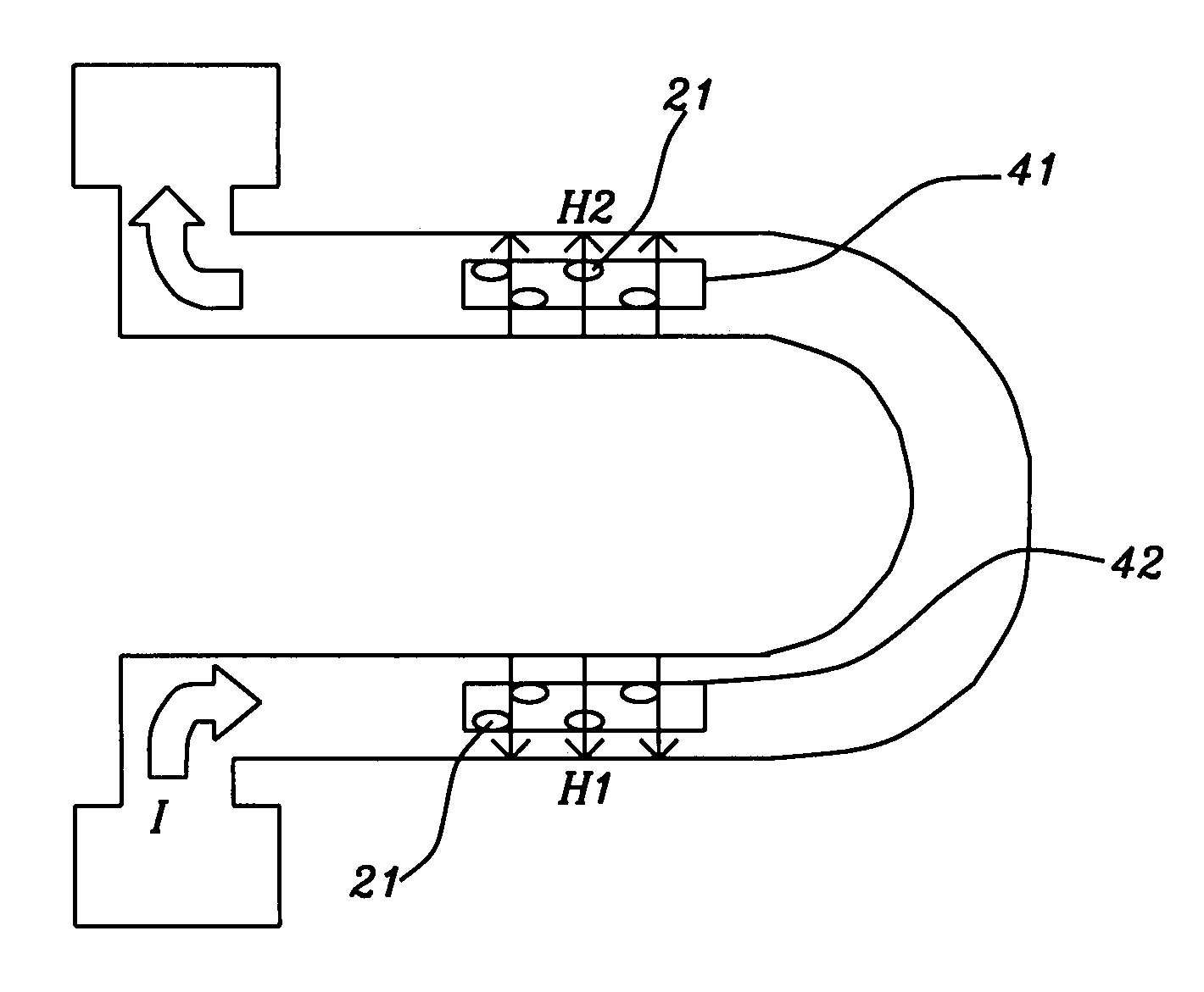
[0024]As noted above, a large external magnetic field (one greater than about 60 Oe) could change the single domain state of the GMR or MTJ free layer into multiple domain states, leading to hysteresis of the magnetic response and causing current reading errors. To address this problem, the prior art device discussed above includes means for giving the free layer magnetization a longitudinal bias. Said means take the form of a pair of permanent or exchange coupled magnets, one such pair for each sensor. Aside from the additional cost that this adds to the manufacturing process use of longitudinal bias will also reduce the sensitivity of the device as well as introducing further degradation due to changes in the permanent bias over time.

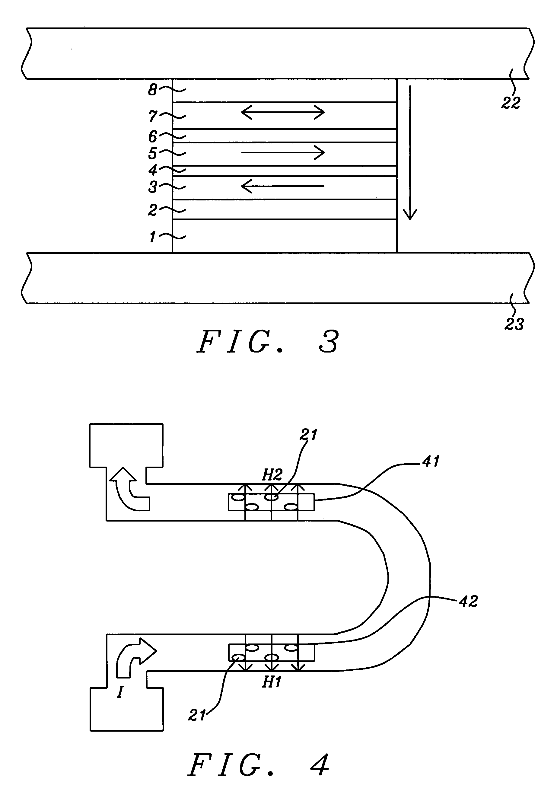
[0025]In a ferromagnetic thin film, magnetic exchange interaction between adjacent grains is so strong that magnetization directions in neighboring grains are aligned or nearly aligned. In a typical free layer film of thickness 2-5 nm, the Neel wall w...


PUM


Abstract

By subdividing the free layer of a GMR/TMR device into multiple sub-elements that share common top and bottom electrodes, a magnetic detector is produced that is domain stable in the presence of large stray fields, thereby eliminating the need for longitudinal bias magnets. Said detector may be used to measure electric currents without being affected by local temperature fluctuations and/or stray fields.

Description

FIELD OF THE INVENTION[0001]The invention relates to the general field of magnetic field detection by MTJ or GMR devices with particular reference to free layer stability.BACKGROUND OF THE INVENTION[0002]The present invention relates to a magnetic field sensor using a highly sensitive MTJ (magnetic tunnel junction) device. Its applications include use as a current sensor capable of sensing very small changes in the current flowing through a conductor.[0003]In a conventional current sensor, the sensing elements are two long GMR (Giant MagnetoResistance) bearing stripes disposed adjacent to a conductor to be measured in an in-plane direction[1,2]. Such a current sensor includes: the conductor bent into a U shape; first and second GMR elements located on the conductor on opposing legs of the U so that a magnetic field generated by a nearby conductor will induce opposite magneto-resistance changes in the two GMR devices; and first and second constant current sources that supply constant...

Claims


Application Information

Patent Timeline
IPC IPC(8): G01R33/02H01L21/00
CPCB82Y25/00B82Y40/00G01R15/205G01R33/093G01R33/098G11B5/3932H01F10/3254H01F10/3277H01F41/302
Inventor GUO, YIMINWANG, PO-KANG
Owner HEADWAY TECH INC
Why Eureka
Try Eureka