Position Sensor

a position sensor and sensor technology, applied in the field of position sensors, can solve the problems of reducing the output sensitivity, deteriorating the detection accuracy, and reducing the sensitivity of the position sensor, so as to achieve smooth displacement

Inactive Publication Date: 2008-10-23
MATSUSHITA ELECTRIC WORKS LTD
View PDF7 Cites 16 Cited by
  • Summary
  • Abstract
  • Description
  • Claims
  • Application Information

AI Technical Summary

Benefits of technology

[0004]In view of the above problems, a primary concern of the present invention is to provide a position sensor that despite of not having a structural design change in a magnetic core and a detection coil, the magnetic core can be smoothly displaced in the detection coil without receiving an external force.

Problems solved by technology

In this kind of position sensor, it is not difficult to imagine that a change in impedance of the detection coil resulting from an external factor other than the displacement of the magnetic core becomes a cause of deteriorating the detection accuracy.
However, as the distance between the inner peripheral surface of the detection coil and the magnetic core increases, a ratio of magnetic fluxes reaching the magnetic core relative to the magnetic fluxes generated from the detection coil decreases, so that a deterioration in sensitivity of the position senor may occur.
Furthermore, there is another problem of reducing a rising amount of output sensitivity relative to an insertion amount of the magnetic core into the detection coil.

Method used


Image

  • Position Sensor
  • Position Sensor
  • Position Sensor

Examples


first embodiment

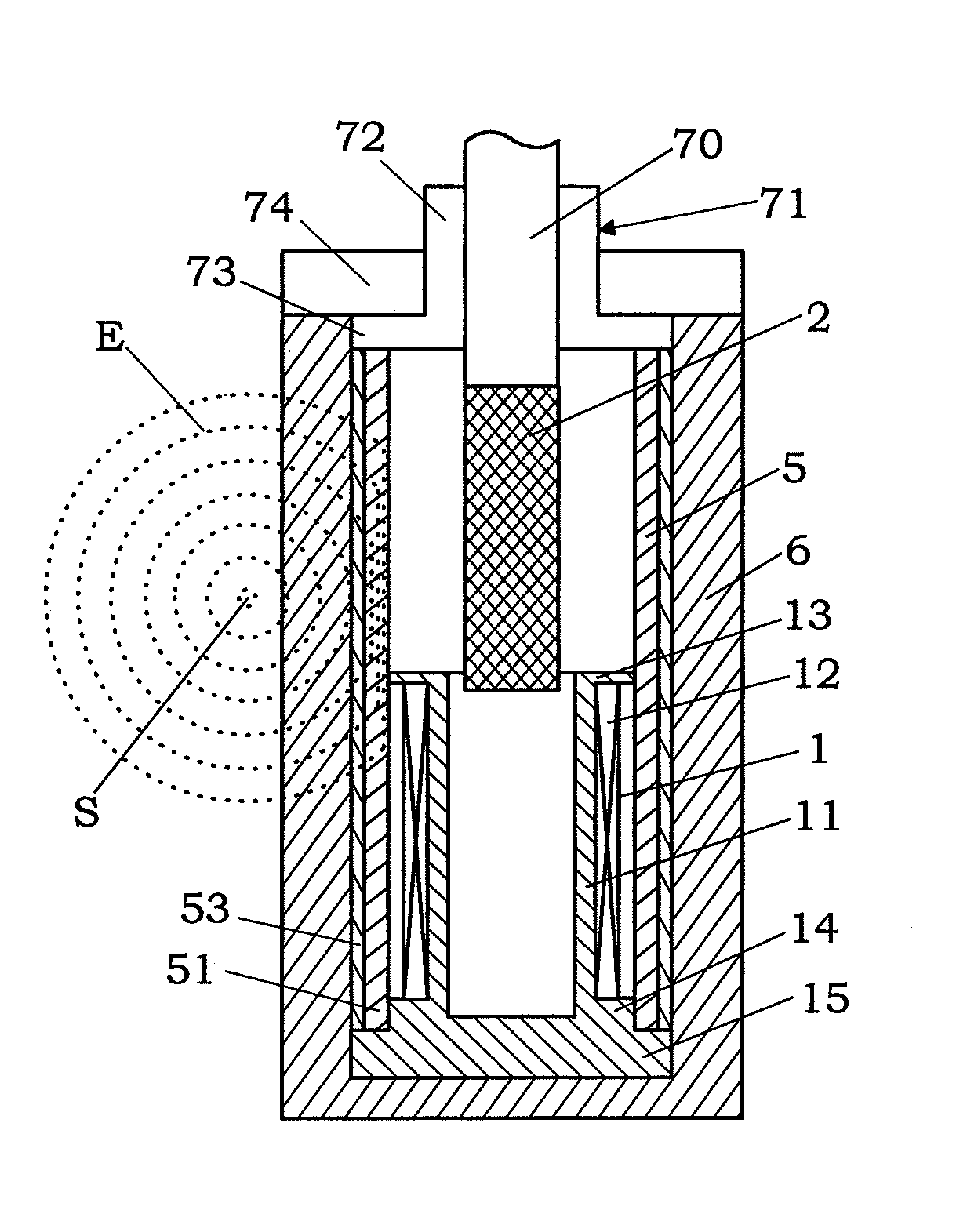
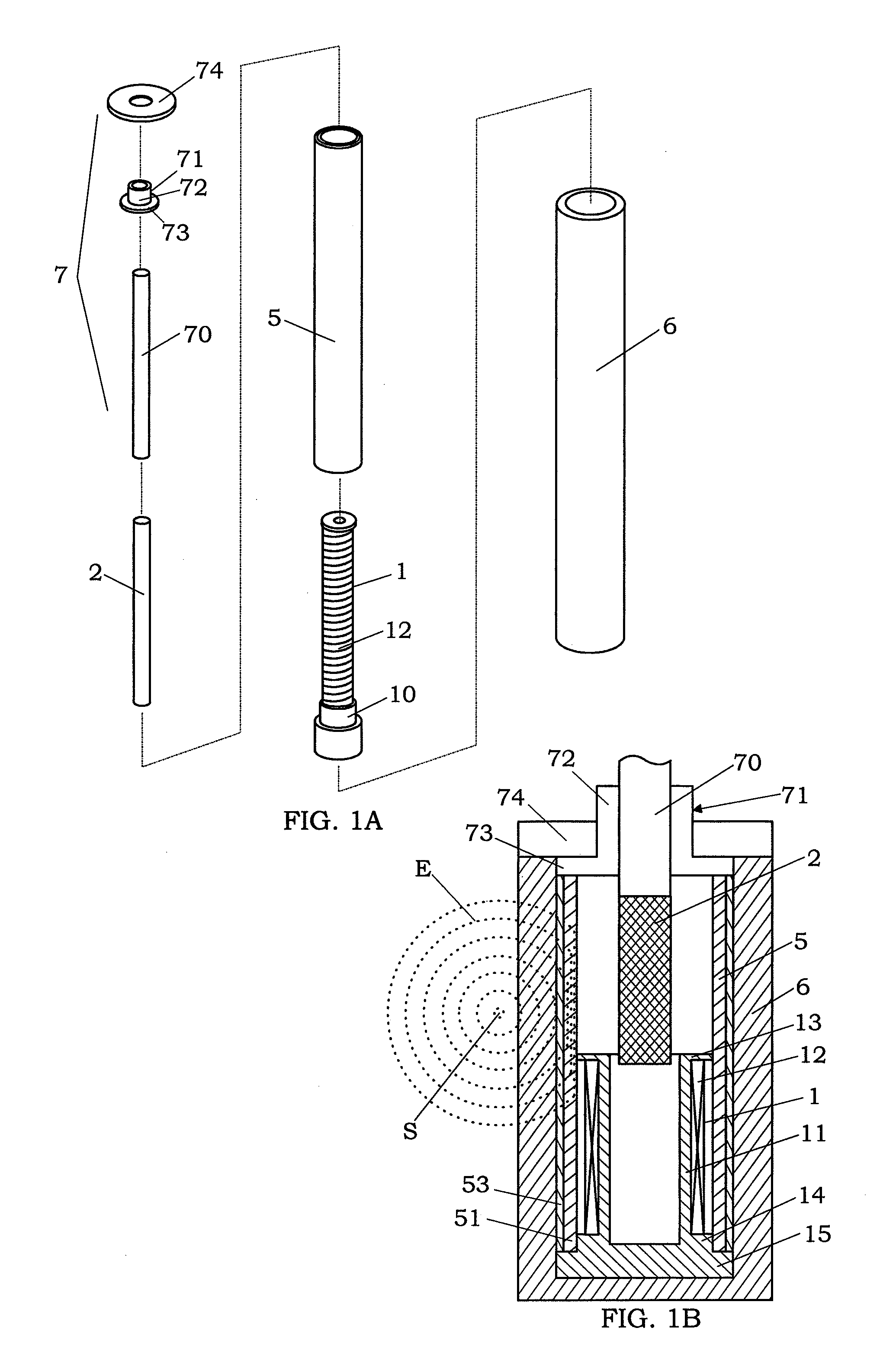
[0035]The present embodiment is characterized by using a guide means comprising guide and support portions with the following features in the position sensor with the basic structure described above. That is, as shown in FIG. 1A, the guide portion of this embodiment is a shaft 70 having an outer diameter substantially equal to the magnetic core 2, and connected to an upper end surface of the magnetic core 2. An upper end surface of the shaft 70 is connected to an object to be detected (not shown). On the other hand, the support portion is provided with a tubular bearing member 71, which is formed such that an outer peripheral surface of the shaft 70 slidably contact an inner surface of the bearing member, and a ring-like cover 74 for securing the bearing member 71 to a predetermined position in the case 6.

[0036]The bearing member 71 is integrally formed with a cylindrical portion 72 having opposite open ends, and a circular flange 73 outwardly extending from a bottom end of the cyli...

second embodiment

[0039]The present embodiment is characterized by using a guide means comprising guide and support portions with the following features in the position sensor with the basic structure described above. That is, as shown in FIG. 4A, the guide portion of this embodiment is provided with a pair of guide bars 20 formed in a columnar shape to extend in substantially parallel with the magnetic core 2, a coupling plate 21 formed in a substantially square shape and used to couple the magnetic core 2 with the guide bars, and a rod-like projection 22 used for a connection with an object to be detected. When the guide bar 20 is formed by a tubular member such as a pipe material, a reduction in weight of the guide portion can be achieved. On the other hand, the support portion 60 of this embodiment attached to one end of the coil bobbin 10 of the detection coil 1 has an opening 61, through which the magnetic core 2 is inserted into the detection coil 1, and guide openings 62, into which the pair ...

third embodiment

[0043]The present embodiment is characterized by using a guide means comprising guide and support portions with the following features in the position sensor with the basic structure described above. That is, as shown in FIGS. 7A and 7B, the support portion 60 of this embodiment has an opening 61, into which the magnetic core 2 is inserted, at one end of the detection coil 1, and a pair of columnar projections 63, which are angularly spaced from each other by substantially 180 degrees around the center axis of the detection coil 1 and extend in substantially parallel to each other in the axial direction of the detection coil 1. On the other hand, the guide portion is provided with a coupling plate 21 having a substantially square shape and a rod-like projection 22 used for a connection with an object to be detected. The coupling plate 21 connected to the magnetic core 2 has guide openings 25, into which the columnar projections 63 are respectively inserted. The pair of the columnar ...


PUM


Abstract

A compact position sensor with high operational reliability is provided. This sensor has a tubular detection coil, a magnetic core movable in the detection coil, a drive circuit for the detection coil, a signal processing circuit for converting a change in impedance of the detection coil into an electric signal, and a guide means for guiding a movement of the magnetic core in the detection coil. The guide means has a guide portion connected to the magnetic core and a support portion for slidably supporting the guide portion. The magnetic core can be smoothly displaced in the detection coil without contacting an inner surface of the detection coil by a sliding movement of the guide portion relative to the support portion.

Description

TECHNICAL FIELD[0001]The present invention relates to a position sensor using a change in impedance of a detection coil caused by a displacement of a magnetic core.BACKGROUND ART[0002]A position sensor, which has the capability of outputting an electrical signal according to a change in impedance of a tubular detection coil caused by a physical displacement of a magnetic core in the detection coil, has been utilized for measurement and control in many technical fields such as internal combustion and electric power facility. In this kind of position sensor, it is not difficult to imagine that a change in impedance of the detection coil resulting from an external factor other than the displacement of the magnetic core becomes a cause of deteriorating the detection accuracy. For example, during the displacement of the magnetic core made of a magnetic metal material such as ferrite in the detection coil, when the magnetic core comes into contact with an inner peripheral surface of the d...

Claims


Application Information

Patent Timeline
Patent Type & Authority Applications(United States)
IPC IPC(8): G01D5/20
CPCG01D3/02G01D5/2013G01D5/20
Inventor NIWA, MASAHISAINOOKA, YUKIKO
Owner MATSUSHITA ELECTRIC WORKS LTD
Why Eureka
Try Eureka