

Display device, method for driving display device, and electronic apparatus
a display device and display method technology, applied in the field of display devices, can solve problems such as color-breakup image problems, difficult user interface, and observer perception of conspicuous flicker, and achieve the effects of suppressing gradation, preventing color breakup, and preventing the occurrence of color breakup
- Summary
- Abstract
- Description
- Claims
- Application Information
AI Technical Summary
Benefits of technology
Problems solved by technology
Method used
Image

Examples
embodiment a1
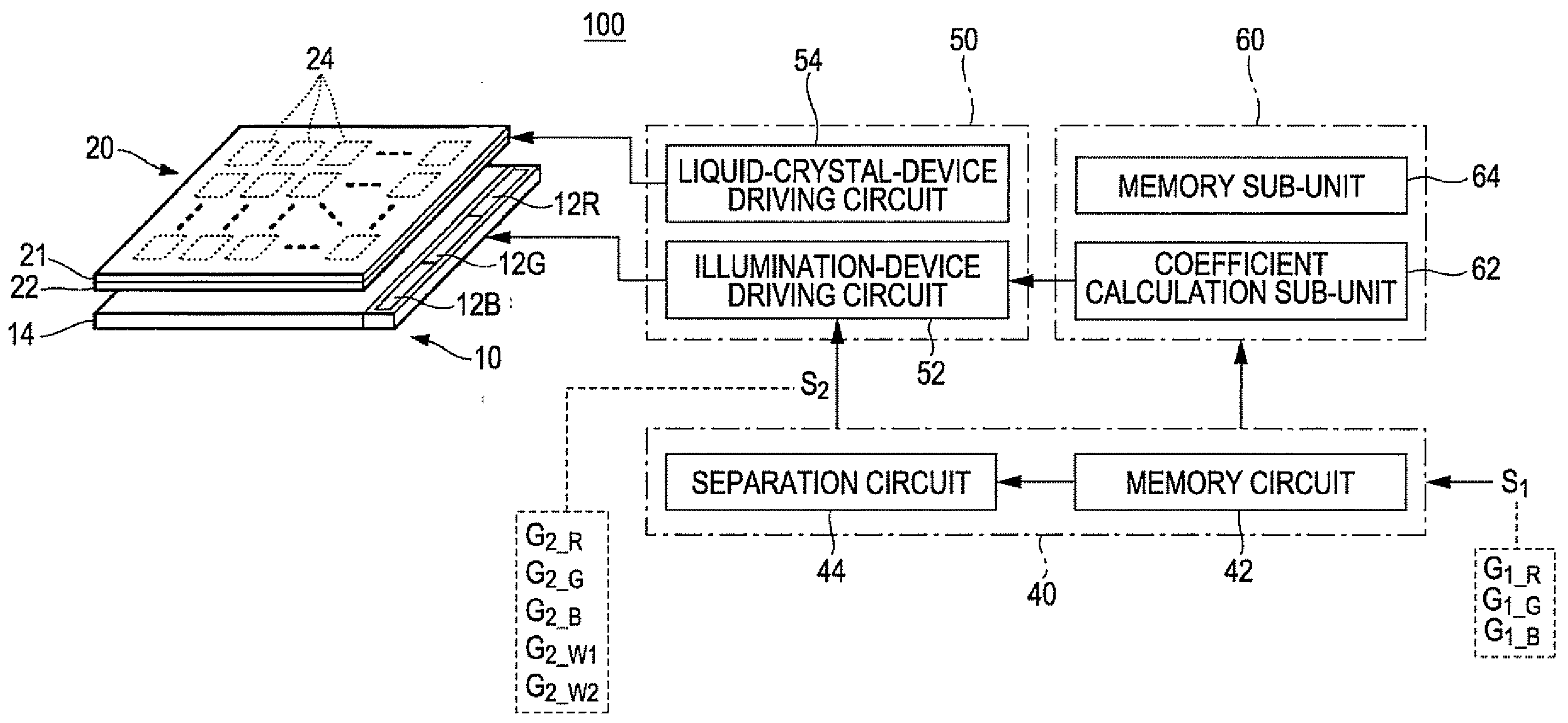
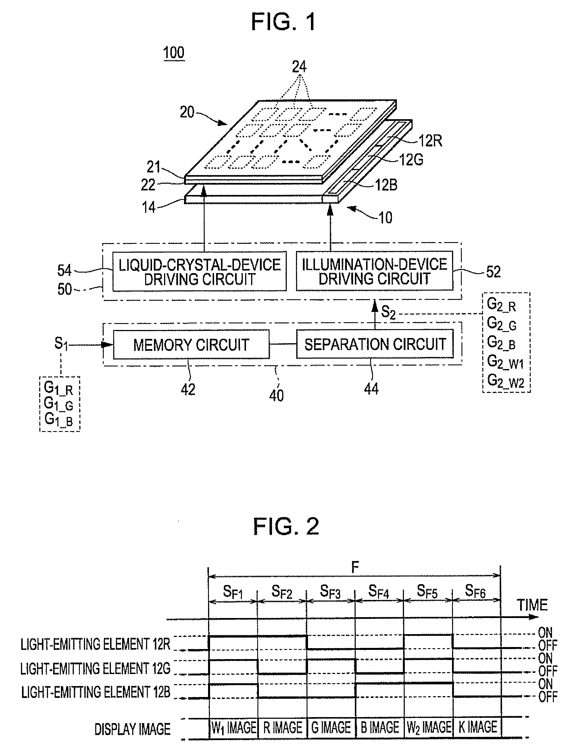
[0097]FIG. 1 is a diagram that schematically illustrates an example of the configuration of a display device according to an exemplary embodiment A1 of the invention. As illustrated in FIG. 1, an image display device 100 is provided with an illumination device 10, a liquid crystal device 20, an image-processing unit 40, and a controlling unit 50. The image-processing unit 40 and the controlling unit 50 may be provided in a single integrated circuit (IC). Or, the image-processing unit 40 may be embodied as a circuit component of one integrated circuit whereas the controlling unit 50 may be embodied as a circuit component of another integrated circuit in a discrete manner.
[0098]The illumination device 10 is provided at the back of the liquid crystal device 20. The illumination device 10 illuminates the liquid crystal device 20. The illumination device 10 has a plurality of light-emitting elements 12 and a light-guiding plate 14, the latter of which is configured as an optical waveguid...
embodiment a2
[0119]Next, an exemplary embodiment A2 of the invention is explained below. In the foregoing exemplary embodiment A1 of the invention, it is explained that a display color specified by the input image signal S1 is separated into a plurality of primary color components and a plurality of white components. In contrast, the image-processing unit 40 of the image display device 100 according to the present embodiment of the invention generates a color separation image signal S2 as a result of the separation of a display color specified by the input image signal S1 into a complementary color component that is formed as a result of the mixture of two primary color components, a plurality of white components, and a primary color component that remains after the mixture of two primary color components. In the following description, the above-described complementary color component that is formed as a result of the mixture of two primary color components is referred to as a “mixed color compo...
embodiment b1
[0131]FIG. 15 is a diagram that schematically illustrates an example of the configuration of a display device according to an exemplary embodiment B1 of the invention. As illustrated in FIG. 15, an image display device 100 is provided with an illumination device 10, a liquid crystal device 20, and a controlling unit 50. For the purpose of illustration, a distance is provided between the illumination device 10 and the liquid crystal device 20 in FIG. 15. However, needless to say, the illumination device 10 and the liquid crystal device 20 are provided close to each other in the actual implementation of the invention.
[0132]As shown in FIG. 15, a rectangular image display area 25 of the liquid crystal device 20 in which images are displayed is made up of two image display sub-areas G1 and G2. These image display sub-areas G1 and G2 are demarcated adjacent to each other as viewed in the Y direction. A plurality of pixel electrodes 24 is arrayed in the image display area 25. The first-me...
PUM
 Abstract
Description
Claims
Application Information