Axial fan apparatus, housing, and electronic apparatus

a technology of axial fan and housing, applied in the direction of wind motor with parallel air flow, wind motor with perpendicular air flow, liquid fuel engine components, etc., can solve the problems of swirling flow and noise generation, and achieve the effect of reducing noise level, reducing noise, and reducing nois

Inactive Publication Date: 2008-10-23
SONY CORP
View PDF33 Cites 16 Cited by
  • Summary
  • Abstract
  • Description
  • Claims
  • Application Information

AI Technical Summary

Benefits of technology

[0007]In order to suppress the noise, the fans should preferably be furth...

Problems solved by technology

The swirling f...

Method used


Image

  • Axial fan apparatus, housing, and electronic apparatus
  • Axial fan apparatus, housing, and electronic apparatus
  • Axial fan apparatus, housing, and electronic apparatus

Examples


Embodiment Construction

[0034]In the following, embodiments of the present invention will be described with reference to the accompanying drawings.

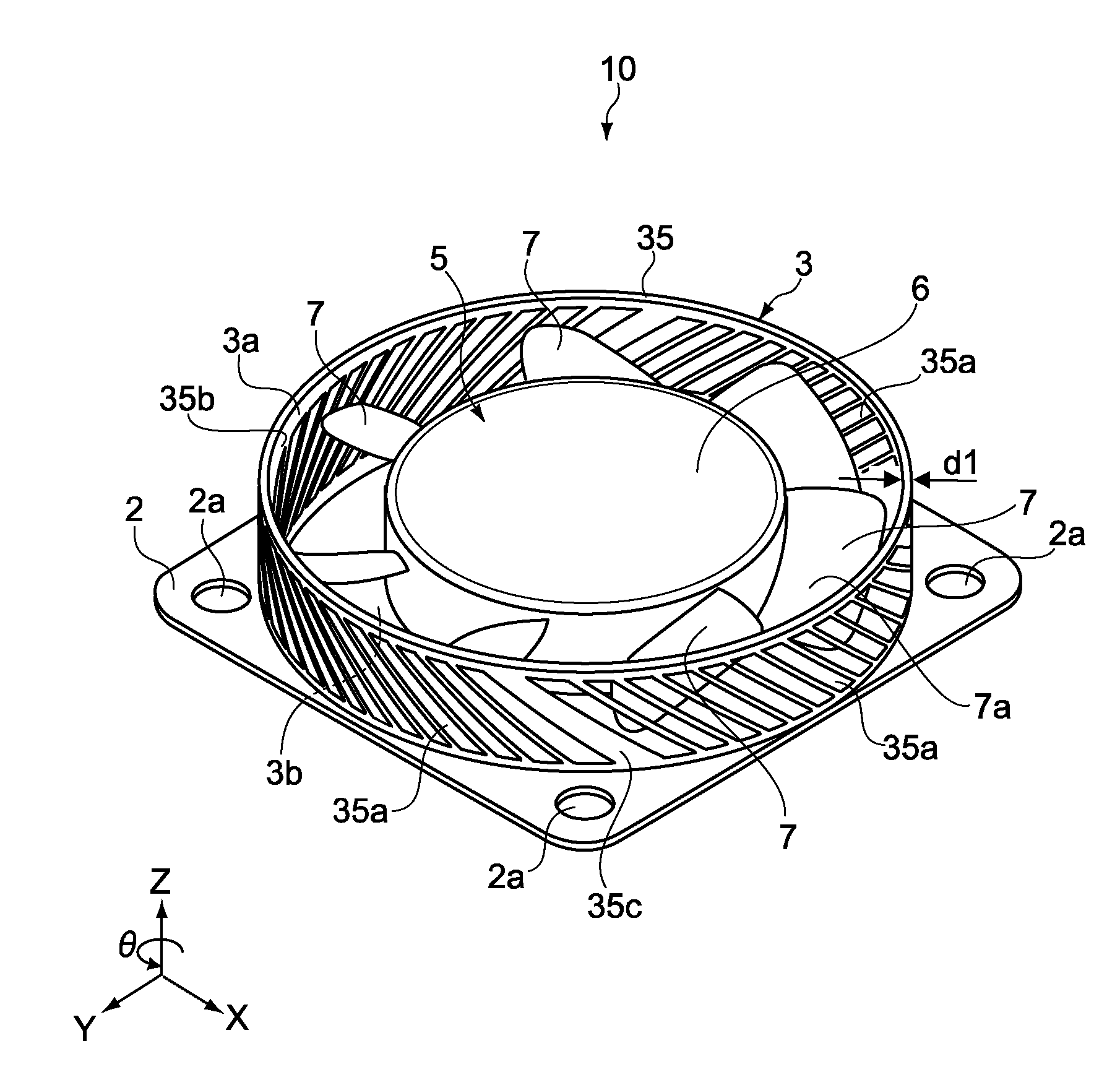
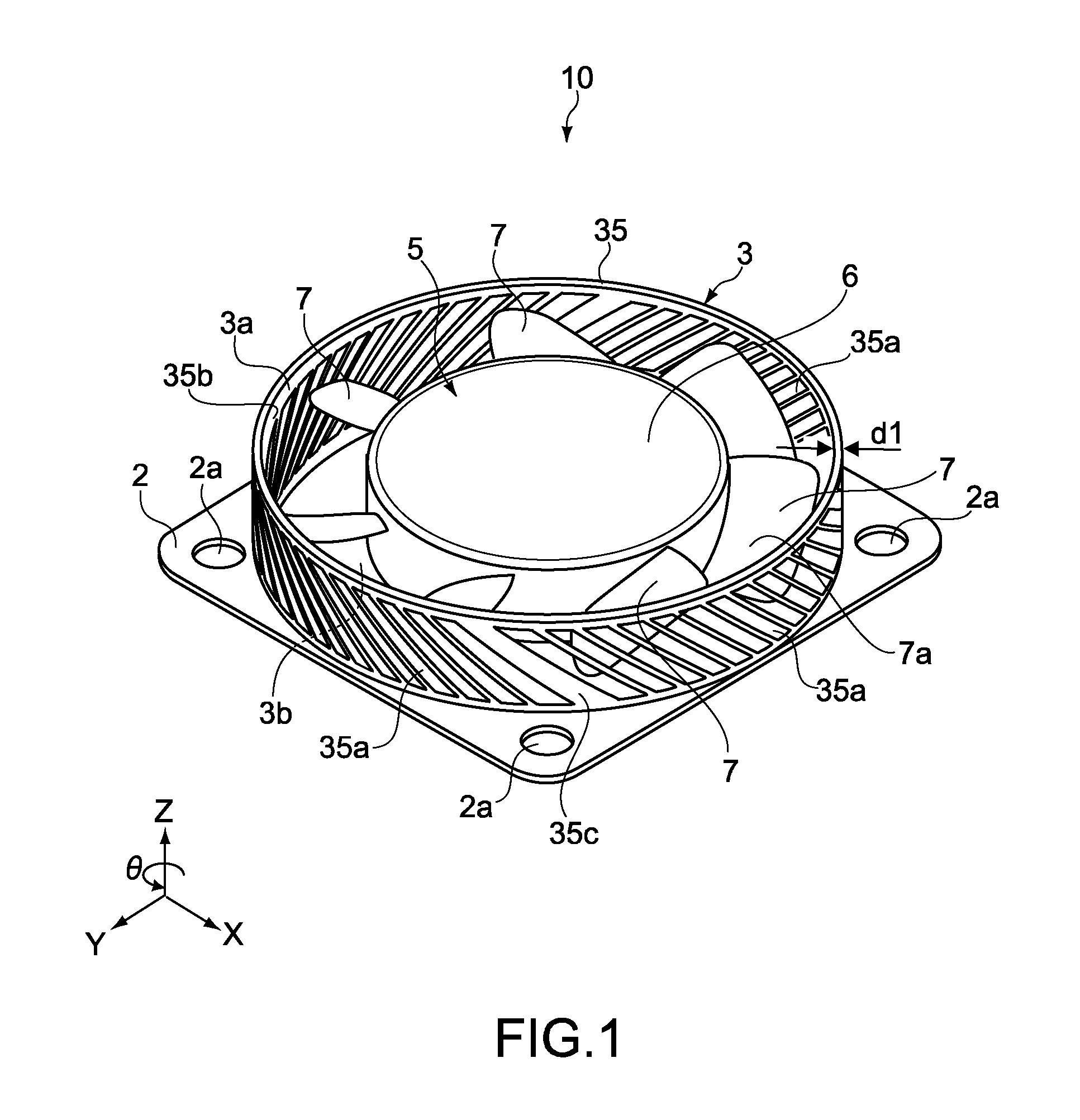
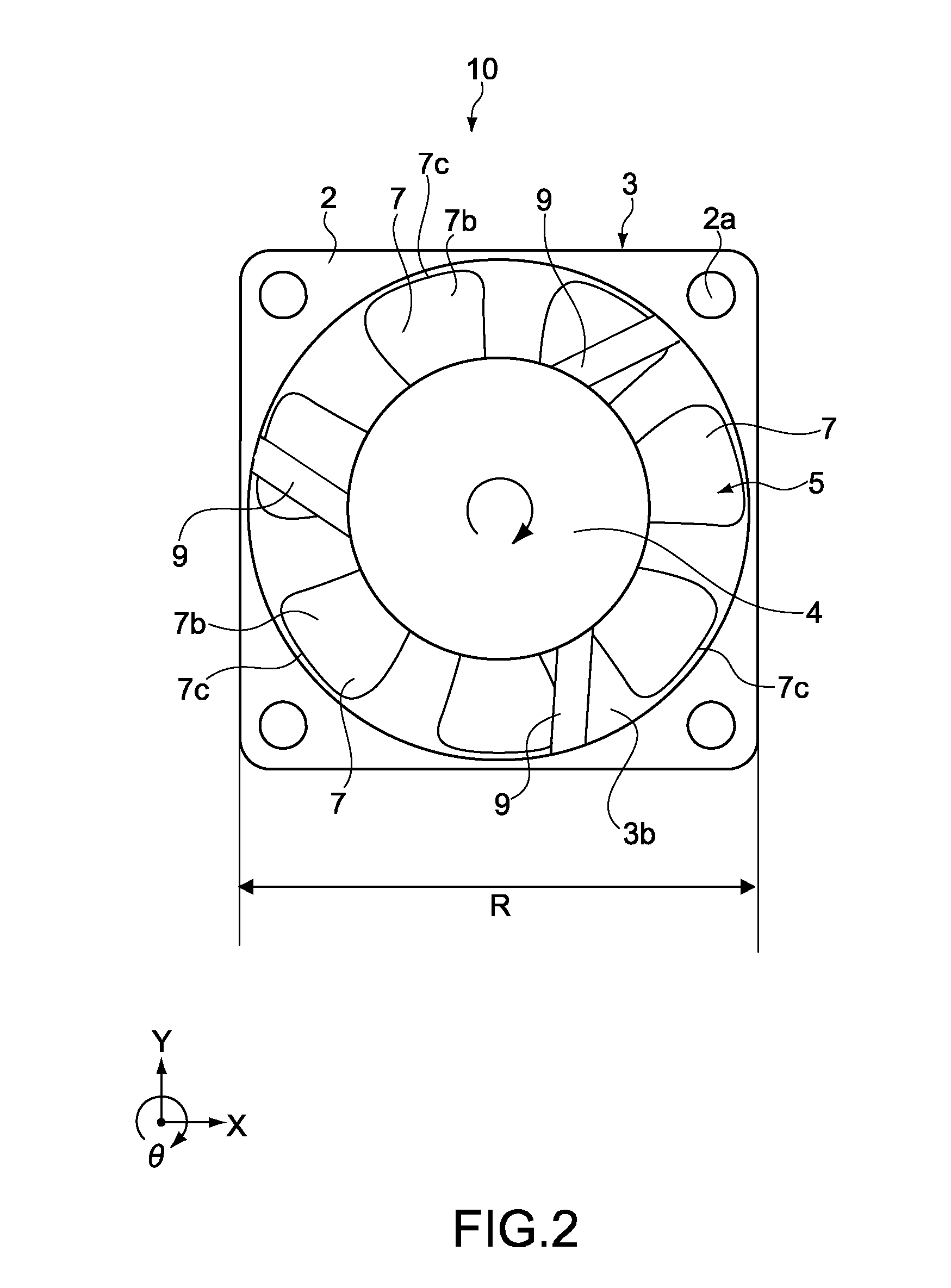
[0035]FIG. 1 is a perspective view showing an axial fan apparatus according to an embodiment of the present invention. FIG. 2 is a plan view showing the axial fan apparatus of FIG. 1, denoted by reference numeral 10, seen from a back surface side thereof. FIG. 3 is a side view of the axial fan apparatus 10.

[0036]The axial fan apparatus 10 includes a housing 3 and an axial-flow impeller 5. The axial-flow impeller 5 is capable of rotating inside the housing 3. The axial-flow impeller 5 includes a boss unit 6 and a plurality of blades 7. A motor (drive unit; not shown) is built in the boss unit 6. The plurality of blades 7 are provided around the boss unit 6.

[0037]The housing 3 includes an annular sidewall 35. An opening at an upper portion of the sidewall 35 serves as a suction port 3a. Airflows in an axial direction (Z direction) generated by the blades 7 rotatin...


PUM


Abstract

There is provided an axial fan apparatus including an axial-flow impeller, a drive unit, and a housing. The axial-flow impeller is capable of rotating and includes a plurality of blades inclined with respect to a rotational axis direction. The drive unit rotates the axial-flow impeller. The housing is mounted with the drive unit, and includes a sidewall, and a plurality of slits that circulate gas. The sidewall is provided around the axial-flow impeller. The plurality of slits are provided to the sidewall and inclined with respect to the rotational axis direction in a direction opposed to a direction in which the plurality of blades incline.

Description

CROSS REFERENCES TO RELATED APPLICATIONS[0001]The present invention contains subject matter related to Japanese Patent Application JP 2007-107749 filed in the Japanese Patent Office on Apr. 17, 2007, the entire contents of which being incorporated herein by reference.BACKGROUND OF THE INVENTION[0002]1. Field of the Invention[0003]The present invention relates to an axial fan apparatus that blows air in an axial-flow direction, a housing that is used for the axial fan apparatus, and an electronic apparatus that is mounted with the axial fan apparatus.[0004]2. Description of the Related Art[0005]Recently, fans are used to cool down heat generators in most electronic apparatuses such as PCs. Herein, it is necessary to increase flow rate of the fans and to reduce noise generated by the operating fans.[0006]Japanese Patent Application Laid-open No. 2001-003900 (paragraphs 0016 and 0017, FIG. 1; hereinafter referred to as Patent Document 1) discloses an axial-flow fan including a housing ...

Claims


Application Information

Patent Timeline
IPC IPC(8): H05K7/20F04D29/52F04D29/38
CPCF04D25/0613F04D29/384F05D2240/307F04D29/164F04D29/685F04D29/542F04D29/663F05D2210/12F05D2260/60Y10S415/00
Inventor KAYAMA, SHUNSHIMIZU, YUKIKOYAMAMOTO, KAZUTOSHI
Owner SONY CORP
Why Eureka
Try Eureka