Heat radiator and electronic apparatus

a technology of electronic equipment and heat radiator, which is applied in the direction of lighting, heating equipment, cooling/ventilation/heating modifications, etc., can solve the problem of large noise, and achieve the effect of maintaining heat radiation performance and reducing nois

Inactive Publication Date: 2008-10-23
FUJITSU LTD
View PDF18 Cites 6 Cited by
  • Summary
  • Abstract
  • Description
  • Claims
  • Application Information

AI Technical Summary

Benefits of technology

[0008]The present invention has been made in view of the above circumstances and provides a heat radiator contributing to decreasing noise maintaining the heat radiation performance, and an electronic apparatus which is equipped with the heat radiator.
[0011]In the heat radiator according to the present invention, among the heat radiation fins arranged at intervals, there are heat radiation fins each having a notch formed in its one edge in at least one of the air inflow side edge and the air outflow side. The notches are formed such that the central parts of the edges of the heat radiation fins are cut alternately or on a circulating basis in an array direction of the heat radiation fins. Therefore, it is possible to make the opening space at the air inflow side and / or the air outflow side larger than a case where heat radiation fins having no such notches are merely arranged at intervals. This makes it possible to reduce collisions between the edges of the fins and air. Since the notches are formed at the edges of the heat radiation fins, the heat radiator of the present invention can suppress nose without lowering the radiation function.
[0013]When the endothermic board, the heat transfer member, or the fan are provided, it is possible to effectively radiate heat by means of the radiation fins.
[0024]As described above, the present invention provides a heat radiator contributing to decreasing noise maintaining the heat radiation performance, and an electronic apparatus which is equipped with the heat radiator.

Problems solved by technology

Here, one big problem in the heat radiator that two or more heat radiation fins like the above-mentioned open the space and are arranged is the points with a large noise.

Method used


Image

  • Heat radiator and electronic apparatus
  • Heat radiator and electronic apparatus
  • Heat radiator and electronic apparatus

Examples


Embodiment Construction

[0049]Embodiments of the present invention will be described with reference to the accompanying drawings.

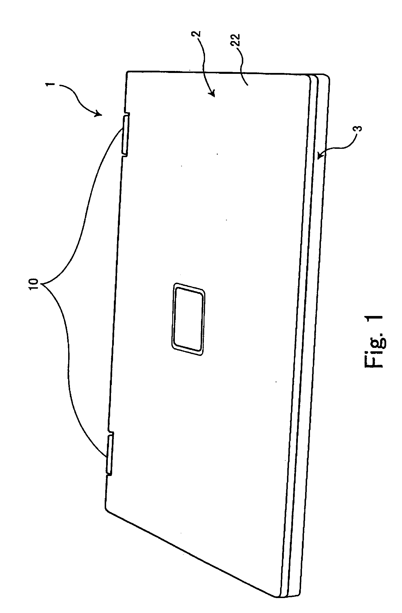
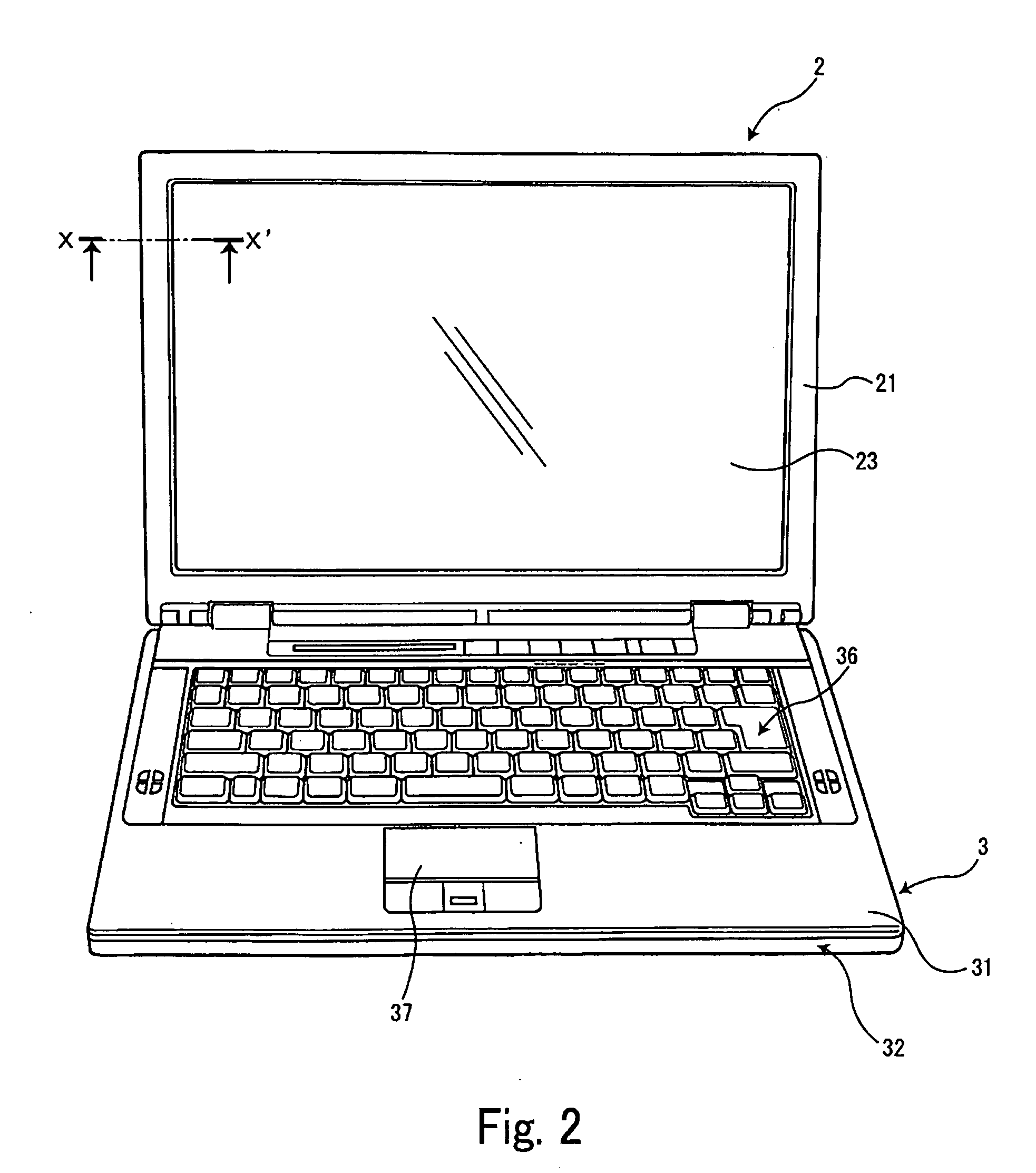
[0050]FIG. 1 and FIG. 2 are each a perspective view of an electronic apparatus according to one embodiment of the present invention.

[0051]A computer 1, which is the present embodiment, is a so-called note type of personal computer, in which an image display unit 2 that accommodates an image display device 23 for displaying an image is connected on a free basis in opening and shutting through hinge members 10 with a main unit 3 that incorporates a circuit substrate and disposes a keyboard on the upper surface.

[0052]FIG. 1 shows a state in which the image display unit 2 shuts to the main unit 3 and is piled up. FIG. 2 shows a state in which the image display unit 2 is opened for the main unit 3.

[0053]The main unit 3 shown in FIG. 1 and FIG. 2 is composed of a keyboard 36 in which two or more keys are arranged, an operation section 37 that consists of a track pad and a click button,...


PUM


Abstract

A heat radiator has two or more heat radiation fins arranged at intervals, and conducts heat from the heat radiation fins to air that flows in space of the heat radiation fins. The heat radiation fins have notches formed such that central parts of edges of the heat radiation fins in at least one of the air inflow side and the air outflow side of the heat radiation fins are cut alternately or on a circulating basis in an array direction of the heat radiation fins.

Description

BACKGROUND OF THE INVENTION[0001]1. Field of the Invention[0002]The present invention relates to a heat radiator having two or more heat radiation fins arranged at intervals, which radiate heat to air that flows in space of the heat radiation fins, from the heat radiation fins, and an electronic apparatus which is equipped with an electric circuit to perform the heat radiation by the heat radiator.[0003]2. Description of the Related Art[0004]The calorific value from large-scale LSI increases as large-scale LSI that has a high arithmetic capacity in an electronic apparatus is installed along with more and more making of an electronic apparatus in recent years high performance, and the arithmetic capacity improves further. Therefore, the height of the heat radiation performance has been demanded from the heat radiator that bears the heat radiation of the large-scale LSI more and more.[0005]As the heat radiator, there is known the one in which the heat generated from large-scale LSI is...

Claims


Application Information

Patent Timeline
Patent Type & Authority Applications(United States)
IPC IPC(8): H05K7/20F28F7/00
CPCG06F1/203G06F1/00G06F1/16G06F1/20H05K7/20
Inventor IWATA, MASAKITACHIKAWA, TADANORI
Owner FUJITSU LTD
Why Eureka
Try Eureka