Switching-mode power converter and pulse-width-modulation control circuit with primary-side feedback control

a technology of power converter and control circuit, which is applied in the direction of pulse manipulation, pulse technique, instruments, etc., can solve the problem of high production cost, and achieve the effect of low cos

Inactive Publication Date: 2008-10-23
LEADTREND TECH
View PDF8 Cites 170 Cited by
  • Summary
  • Abstract
  • Description
  • Claims
  • Application Information

AI Technical Summary

Benefits of technology

[0006]It is therefore one of the objectives of the present invention to provide a switching-mode power converter and related PWM c

Problems solved by technology

Although the above-mentioned output voltage Vo can be precisely regulated by the flyback converter 100, the p

Method used


Image

  • Switching-mode power converter and pulse-width-modulation control circuit with primary-side feedback control
  • Switching-mode power converter and pulse-width-modulation control circuit with primary-side feedback control
  • Switching-mode power converter and pulse-width-modulation control circuit with primary-side feedback control

Examples


first embodiment

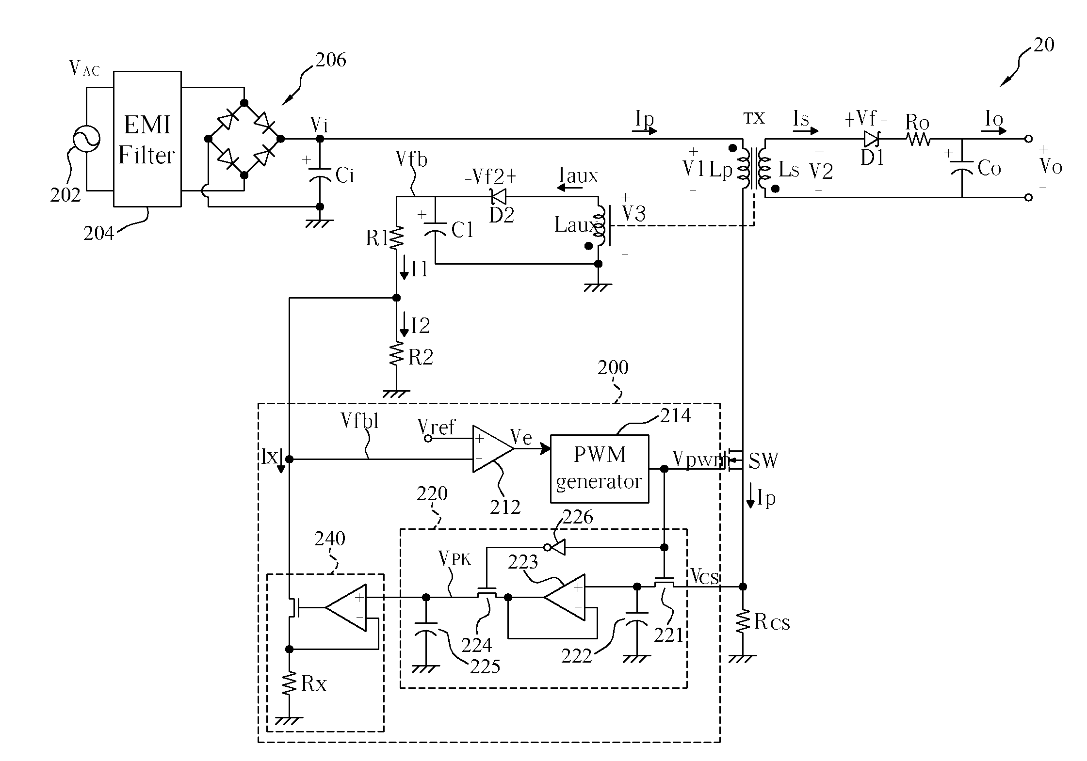
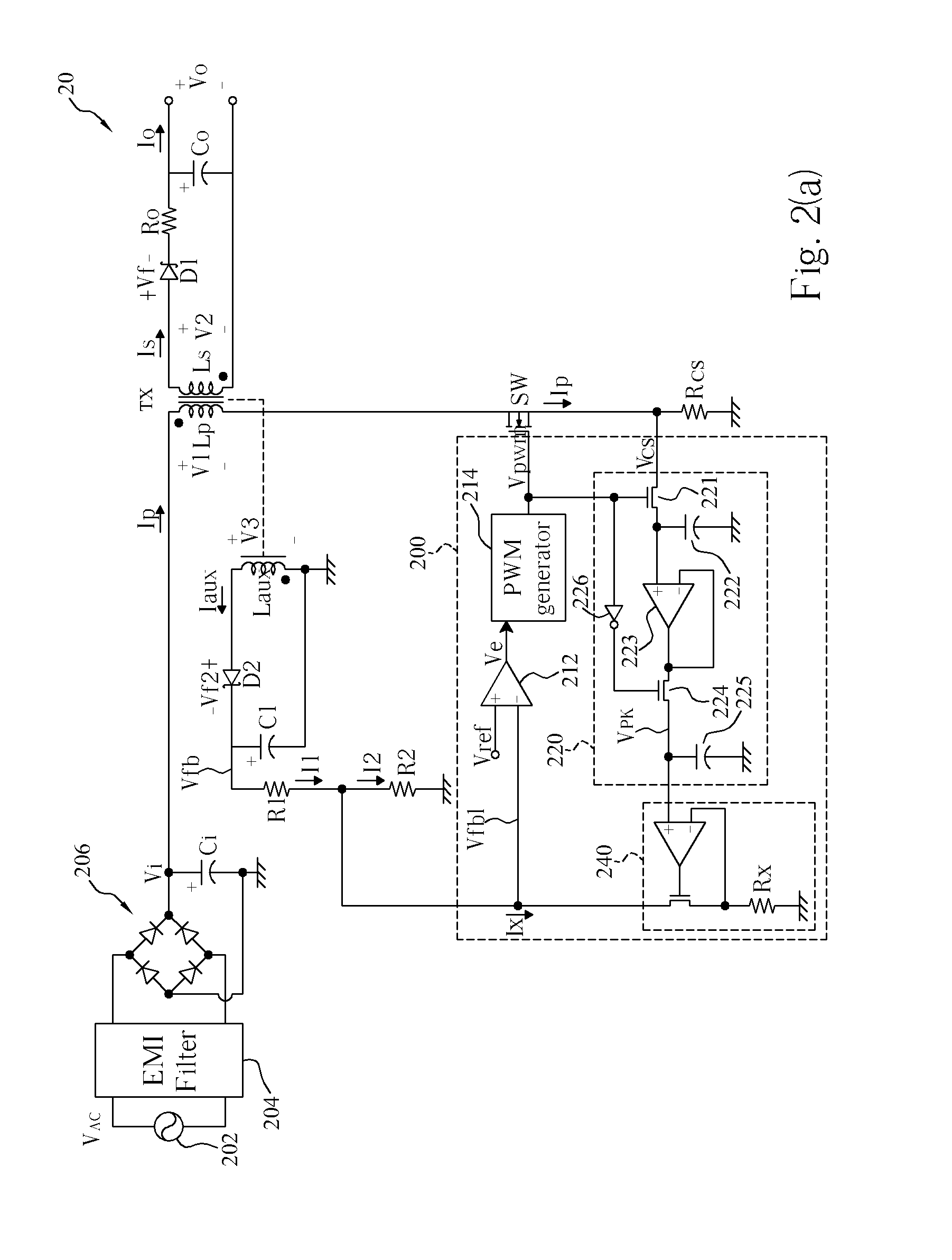
[0016]FIG. 2(a) is a diagram of a switching-mode power converter 20 according to the present invention. An AC voltage VAC provided from an AC voltage source 202 is respectively filtered and rectified by an EMI filter 204 and a bridge rectifier 206, for generating a DC input voltage Vi. The DC input voltage Vi is coupled to a primary-side winding Lp of a transformer TX, and a power switch SW is connected to the primary-side winding Lp of the transformer TX in series. A PWM generator 214 is utilized for generating a PWM signal Vpwm to turn on / off the power switch SW, for transforming the input voltage Vi into an output voltage Vo.

[0017]FIG. 2(b) is a waveform diagram illustrating the PWM signal Vpwm, a primary-side winding current Ip, and a secondary-side winding current Is shown in FIG. 2(a) when the switching-mode power converter 20 operates in Discontinuous Conduction Mode (DCM). As shown in FIG. 2(b), waveforms 200b, 202b, and 204b are representative of the PWM signal Vpwm, the pr...

second embodiment

[0036]Please refer to FIG. 3(a) in conjunction with FIG. 3(b). FIG. 3(a) is a diagram of a switching-mode power converter 30 according to the present invention. FIG. 3(b) is a waveform diagram showing a PWM signal Vpwm, a primary-side winding current Ip, and a secondary-side winding current Is shown in FIG. 3(a) when the switching-mode power converter 30 operates in Continuous Conduction Mode (CCM). As shown in FIG. 3(b), waveforms 300b, 302b, and 304b are representative of the PWM signal Vpwm, the primary-side winding current Ip, and the secondary-side winding current Is respectively. During an on-duty period Ton of the PWM signal Vpwm, a power switch SW is conductive and the primary-side winding current Ip increases gradually from an initial current IP0 to a peak current IPK. During an off-duty period Toff of the PWM signal Vpwm, the power switch SW is turned off and energy stored in the primary-side winding Lp is transferred to the secondary-side winding Ls. Accordingly, the seco...


PUM


Abstract

A pulse-width-modulation control circuit of a switching-mode power converter with a primary-side feedback control is disclosed. The switching-mode power converter includes a transformer, a power switch, a current sensing resistor and the pulse-width-modulation control circuit. The transformer includes a primary-side winding, a secondary-side winding and an auxiliary winding. The pulse-width-modulation control circuit includes a sample and hold circuit, a transconductor circuit, an error amplifier and a pulse-width-modulation generator.

Description

BACKGROUND OF THE INVENTION[0001]1. Field of the Invention[0002]The present invention relates to a switching-mode power converter and a pulse-width-modulation (PWM) control circuit, and more particularly, to a switching-mode power converter with a primary-side feedback control and PWM control circuit thereof.[0003]2. Description of the Prior Art[0004]Please refer to FIG. 1. FIG. 1 is a diagram of a conventional flyback converter 100. An AC voltage VAC provided from an AC voltage source 101 is filtered and rectified respectively by an Electro-Magnetic Interference (EMI) filter 102 and a bridge rectifier 104, and a DC input voltage Vi having ripples is then obtained. The DC input voltage Vi is coupled to a primary-side winding Lp of a transformer TX, and a power switch SW is connected to the primary-side winding Lp of the transformer TX in series. A controller 106 is utilized for outputting a pulse-width-modulation signal Vpwm to turn on / off the power switch SW, for transforming the i...

Claims


Application Information

Patent Timeline
IPC IPC(8): H02M3/335H03K3/017
CPCH02M3/335H02M3/33523H03K3/017
Inventor WEI, DA-CHUNCHANG, YUAN-WEN
Owner LEADTREND TECH
Why Eureka
Try Eureka