
Device for supplying coolant into a shank of a rotary tool as well as a rotary tool, in particular a drill

a technology of rotary tools and coolants, which is applied in the direction of tool workpiece connection, manufacturing tools, transportation and packaging, etc., can solve the problems of undesirably high flow turbulence, high production cost, and inconvenient installation of the device, etc., to achieve simple and cost-advantageous manufacture, simple and convenient installation, and good sealing

Active Publication Date: 2008-10-23
KENNAMETAL INC
View PDF14 Cites 11 Cited by
  • Summary
  • Abstract
  • Description
  • Claims
  • Application Information

AI Technical Summary

Benefits of technology

[0009]An object of at least one possible embodiment of the present application is to essentially guarantee or promote a safe and reliable coolant supply, with minimum-quantity lubrication or a minimized quantity of lubrication, keeping the constructive expenditure low.SUMMARY

Problems solved by technology

The production of the conical design of the shank end with the transverse channel requires a relatively high expenditure.
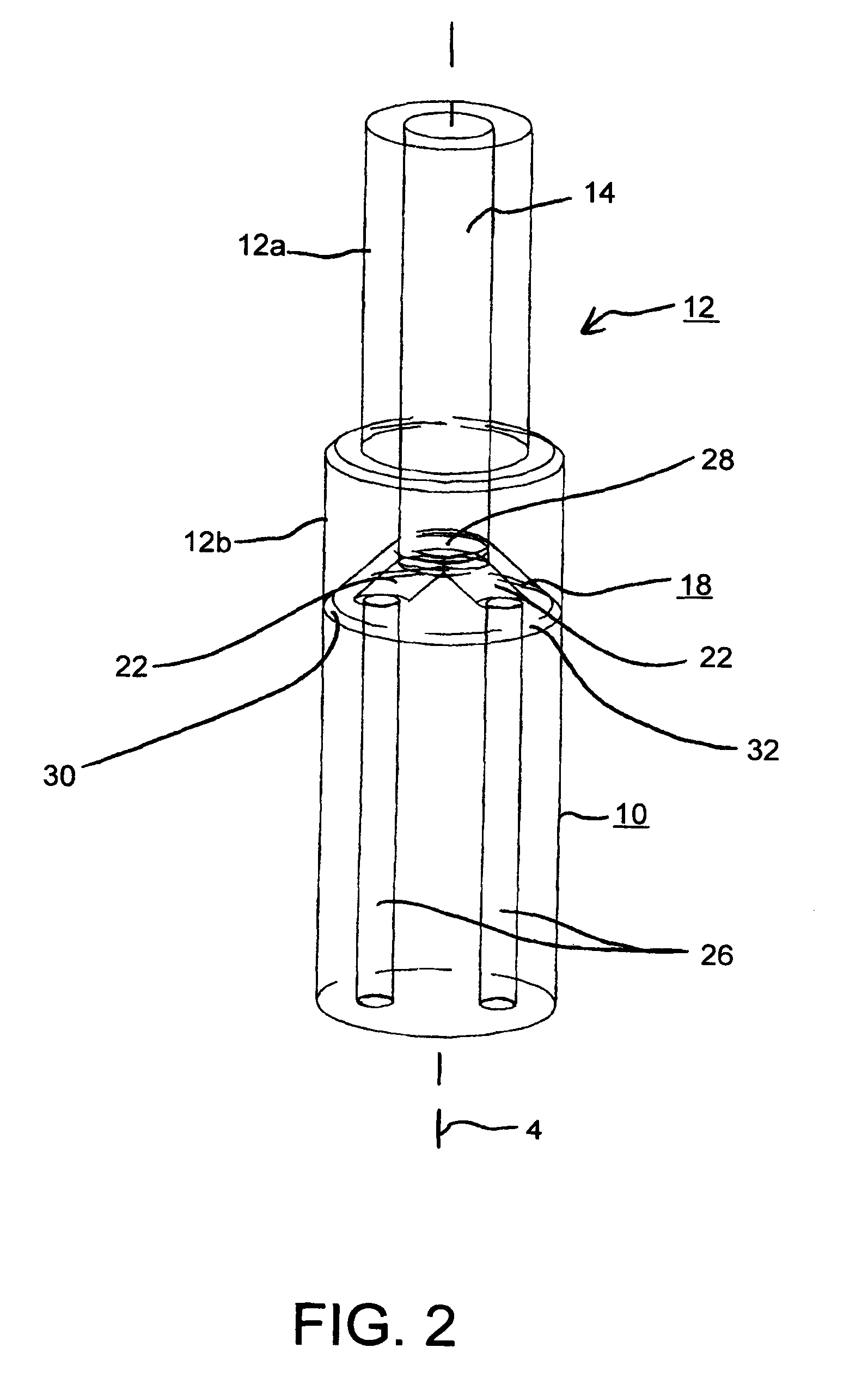
As the latter is designed as a separate element, i.e. an element which is not integrally connected with the adjusting element, the distributing element can have relatively complex geometries at low manufacturing costs.
Furthermore, in at least one possible embodiment of the present application, the two channels extend from the central inlet opening obliquely outwards without bends, or without substantial bends, i.e. in the diversion area inside the distributing element, there are no abrupt turns and no 90° turns, which might lead to undesirably high flow turbulences and thus also to a demulsification.

Method used


Image

  • Device for supplying coolant into a shank of a rotary tool as well as a rotary tool, in particular a drill
  • Device for supplying coolant into a shank of a rotary tool as well as a rotary tool, in particular a drill
  • Device for supplying coolant into a shank of a rotary tool as well as a rotary tool, in particular a drill

Examples


Embodiment Construction

[0032]In the figures, parts having the same effect or features are marked with the same reference numbers.

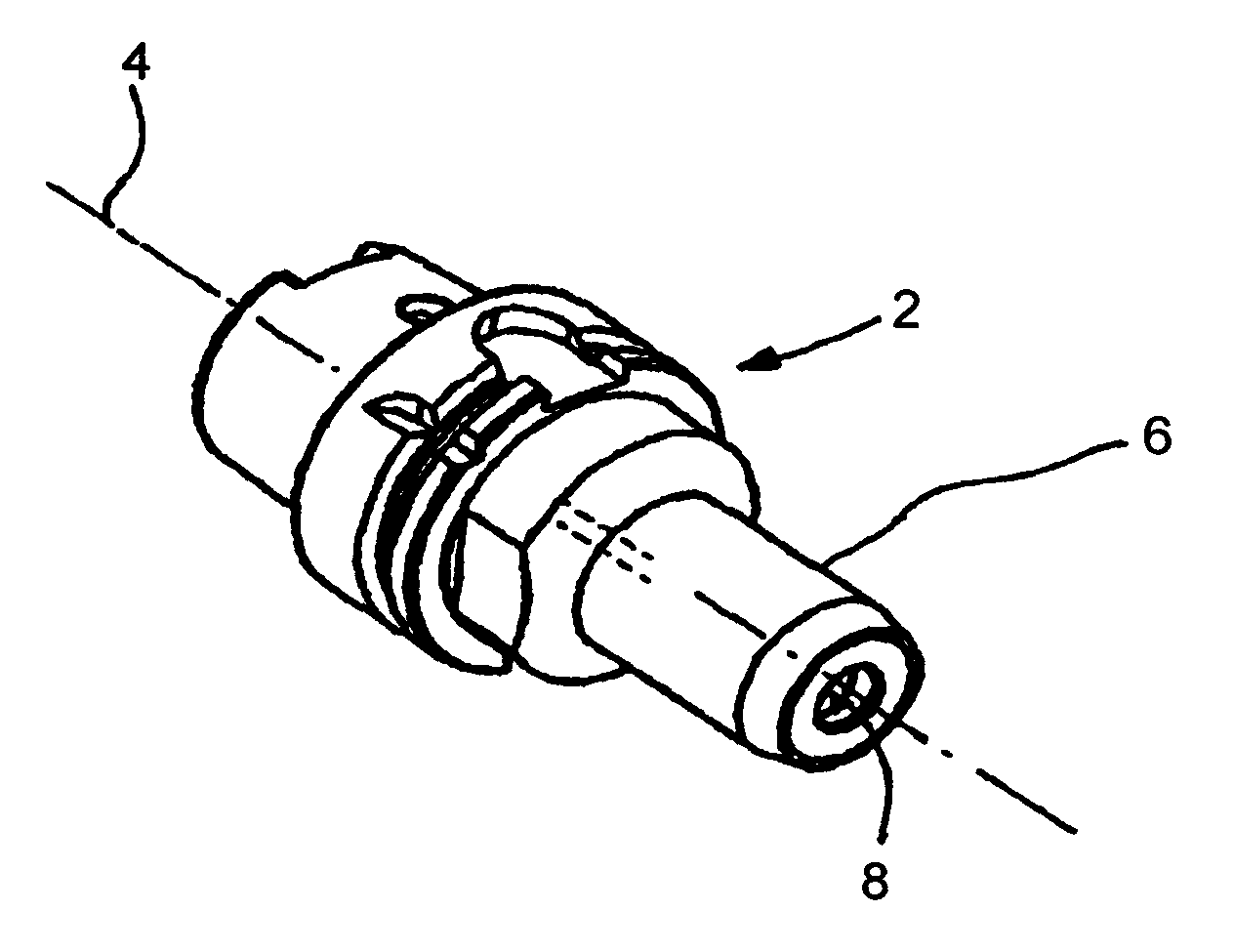
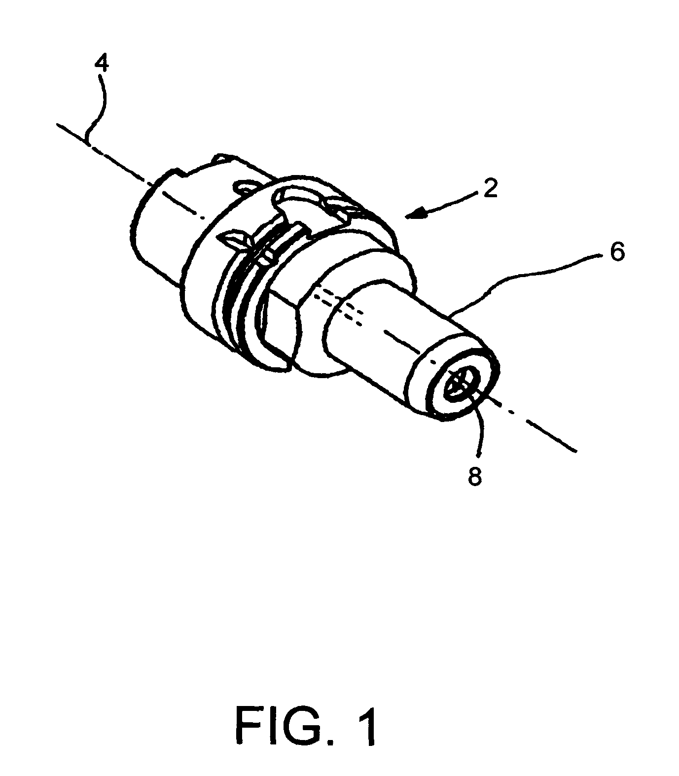
[0033]According to FIG. 1, a chuck 2 extends in axial direction 4 from a rear end to a front-side tool adaptor 6. The tool adaptor 6 includes a clamping hole 8 for the insertion of the shank 10 of a drill or a twist drill. Only the shank 10 of this drill is shown in FIG. 2 to 5. The chuck 2 shown in FIG. 1 is designed as a so-called expansion chuck.

[0034]FIGS. 2 to 4 show different views of an adjusting element 12 with an end of the shank 10, part of which is shown. The adjusting element 12 is arranged in the chuck 2, adjacent to the clamping hole 8, and is usually displaceable in axial direction 4.

[0035]In the embodiment shown, the adjusting element 12 is designed in the manner of a cylindrical tube and comprises a rear partial area 12a, on the front side of which, in the direction of the shank 10, a front partial area 12b including a thickened wall area is adjacent. The adjust...


PUM

PropertyMeasurementUnit
Currentaaaaaaaaaa
Digital informationaaaaaaaaaa
Diameteraaaaaaaaaa

Abstract

A device for supplying coolant into a shank of a rotary tool as well as a rotary tool, in particular a drill. The abstract of the disclosure is submitted herewith as required by 37 C.F.R. §1.72(b). As stated in 37 C.F.R. §1.72(b): A brief abstract of the technical disclosure in the specification must commence on a separate sheet, preferably following the claims, under the heading “Abstract of the Disclosure.” The purpose of the abstract is to enable the Patent and Trademark Office and the public generally to determine quickly from a cursory inspection the nature and gist of the technical disclosure. The abstract shall not be used for interpreting the scope of the claims. Therefore, any statements made relating to the abstract are not intended to limit the claims in any manner and should not be interpreted as limiting the claims in any manner.

Description

CONTINUING APPLICATION DATA[0001]This application is a Continuation-In-Part application of International Patent Application No. PCT / EP2006 / 009728, filed on Oct. 9, 2006, which claims priority from Federal Republic of Germany Patent Application No. 10 2005 048 635.5, filed on Oct. 11, 2005. International Patent Application No. PCT / EP2006 / 009728 was pending as of the filing date of this application. The United States was an elected state in International Patent Application No. PCT / EP2006 / 009728.BACKGROUND[0002]1. Technical Field[0003]This application relates to a device for supplying coolant into a shank of a rotary tool as well as a rotary tool, in particular a drill.[0004]2. Background Information[0005]In many existing rotary tools, for example milling cutters, reamers and drills, usually a coolant supply for lubricating and cooling the tool cutting edges is provided. In case of a central coolant supply, the coolant is supplied to the tool through a central coolant channel provided ...

Claims


Application Information

Patent Timeline
IPC IPC(8): B23B51/06B23B27/10B23Q11/12
CPCB23B31/028B23B51/06B23B2240/21B23B2250/12B23Q11/10Y10T279/17111Y10T408/45Y10T409/30952Y10T408/455Y10T408/44Y10T409/304032B23Q11/1023
Inventor KAMMERMEIER, DIRK
Owner KENNAMETAL INC
Learn More